background image

(BLANK)

53

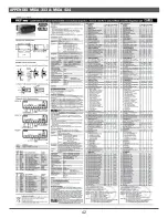
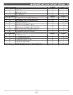
CONTROLLER SET POINT FACTORY SETTINGS (

°

F)

PROBE PARAMETERS

DEFAULT

ACTUAL

/5

Select °C/°F

0

1

/6

Disable decimal point

0

1

/C

Probe Calibration

0

0

ALARM PARAMETERS

DEFAULT

ACTUAL

AL

Low Temperature Alarm Threshold/Deviation

0

0

AH

High Temperature Alarm Threshold/Deviation

0

0

A4

Digital input configuration

10

10

Ac

High Condenser Temperature Alarm

60

140

AE

High Condenser Temperature Alarm Differential

5

4

Acd

High condenser temperature alarm delay [min]

0

5

Ad

Low and high temperature alarm delay

0

5

FAN PARAMETERS

DEFAULT

ACTUAL

F0

Fan Management

0

0

F1

Fan Shutdown Temperature

5

60

F2

Fans Off When Compressor Off

1

0

F3

Fans Status During Defrost

1

0

Fd

Off for Post-Dripping Active for Each val. of F0 [min]

1

0

Summary of Contents for Hillphoenix MIDA

Page 1: ...d that Hillphoenix display cases be installed serviced by qualified and certified technicians who have experience working with commercial refrigerated display merchandisers and storage cabinets For a list of Hillphoenix authorized installation service contractors please visit our Web site www hillphoenix com WARNING FOR YOUR SAFETY Do not store or use gasoline or other flammable vapors and liquids...

Page 2: ...s a potential safety risk for refrigerated case users and or the refrigerated case itself the possible consequences being damage to the case and or serious injury to workers IMPORTANT At Hill PHOENIX the safety of our customers and employees as well as the ongoing performance of our products are top priorities To that end we includeimportantwarningmessagesinallHillPHOENIXinstallationandoperations ...

Page 3: ...1 Rev Date Change Description Author 4 21 compressor compartment diagram parts list electrical diagrams and troubleshooting D Drillion ...

Page 4: ...scharge air temperature values represent readings taken within the upper air channel immediately behind upstream of the honeycomb Rev Date Rev Rev Title 10 28 22 4 DATA UPDATE 04 21 22 3 NOTES UPDATE ENGINEERED FOR STORES WITH AMBIENT CONDITIONS NOT TO EXCEED 75 AND 55 RELATIVE HUMIDITY DUE TO ENGINEERING IMPROVEMENTS SPECIFICATIONS MAY CHANGE WITHOUT NOTICE ALL MEASUREMENTS ARE TAKEN PER ASHRAE 7...

Page 5: ...3 TECHNICAL DATA MIDA Mobile Single Deck Self Contained Mercchandiser 3 X3 4 X4 4 X8 ...

Page 6: ...S WITH AMBIENT CONDITIONS NOT TO EXCEED 75 AND 55 RELATIVE HUMIDITY DUE TO ENGINEERING IMPROVEMENTS SPECIFICATIONS MAY CHANGE WITHOUT NOTICE ALL MEASUREMENTS ARE TAKEN PER ASHRAE 72 2005 SPECIFICATIONS HILLPHOENIX REFRIGERATED DISPLAY CASES FOR SALE IN THE UNITED STATES MEET OR EXCEED DEPARTMENT OF ENERGY 2017 REQUIREMENTS NUMBERS ARE BASED ON STANDARD CASE SIZES CONSULT ENGINEERING ...

Page 7: ...ons This is a self service open single deck merchan dise refrigerated display case with R 290 refrigerant STORE CONDITIONS Hillphoenix cases are designed to operate in an air conditioned store that maintains a 75 F 24 C store temperature and 55 max relative humidity CRMA conditions Case operation will be adversely affected by exposure to excessively high ambient temperatures and or humidity REFRIG...

Page 8: ...sources Excessive Heat 4 Windows 5 Sun 6 Flood lamps 8 feet or less from the product 7 Other heat sources TRANSPORT AND HANDLING The display case is shipped wrapped in plastic sheeting and secured to a pallet or in a wooden crate OPTIONAL To avoid damage during the various stages of shipping and handling it is good practice to keep the display case fully packaged until it is positioned for fi nal ...

Page 9: ...CASE INSTALLATION 7 Positioning the Cabinet Respect the conditions shown in the fi gures below and the indications in TECHNICAL DATA ...

Page 10: ...RAM D A N G E R Electrical equipment and water drainage points are located underneath the display case Do not use front panels and uprights as lift points N O T E Failure to properly level the case could result in lack of proper condensation drainage leading to failure of the unit N O T E Do not obstruct ventilation around the base of the display case condensing unit Obstructing could cause the ca...

Page 11: ...Power Supply 1 Ensure the case power switch is in the off position 2 Plug the main power cord Fig 6 located at the rear base panel of the case into the power source 3 Turn the power switch to the ON position Fig 7 The case should begin normal operations ELECTRICAL Electrical hookups are made through the electrical raceway that can be accessed by removing the front lower panels of the display case ...

Page 12: ...ic controller Picture Function Operates On Adjusts switch on off Power supply to control panel thermostat switch on off Condensing unit motor Adjustment Case Temperature Defrost cycle N O T E See Appendix for full instructions on how to program the Carel electronic controller D A N G E R ALWAYS CHECK THE THERMOSTAT CURRENT RATING because it may have a limited current as low as 2A If necessary prot...

Page 13: ...S 11 SAFETY LABELS Inspect the refrigerated display case and ensure all safety warnings information applied on the refrigerated case are not removed Any labels removed must be replaced The following signs are applied ...

Page 14: ...e you verified the display case switch is in the OFF position prior to plugging in to the main power source see pg 8 Have you reviewed safety warning labels and verified all are present and in good condition see pg 10 After powering up the case be certain that all of the steps listed below have been completed to ensure proper case functionality safety and compliance with warranty terms Check case ...

Page 15: ...ock when refilling the cabinet with new products Older products must be sold first Products must not obstruct air vents Fig 11 Fig 12 N O T E Proceed to the loading only once the display case has reached the proper temperature setting F O R B I D D E N DO NOT OVERLOAD THE CASE this is the most common error and can cause secondary faults and malfunctions e g blocking the evaporator by obstructing c...

Page 16: ...ame frequency where the display case is exposed to fluid spillage or liquid drainage from merchandised products All surfaces pitch downward to a deep drawn drain trough funneling liquids to the center of the case where the waste outlet is located for easy access Check the waste outlet to ensure it is not clogged before starting the cleaning process and avoid introducing water faster than the case ...

Page 17: ... 6 months Remove the lateral panels and clean the tank see Fig 15 Ensure you disconnect the electrical power supply and make sure you DO NOT touch the elements as they reach high temperatures necessary for evaporation inside the tank Cleaning the condenser of the condensing unit The condensers used on the condensing units gather dust and dirt and must be cleaned regularly Under normal working con ...

Page 18: ...CASE CLEANING 16 SCHEDULED MAINTENANCE TABLE Fig 17 Recommended Cleaning Schedule ...

Page 19: ...maximum load level The Refrigerated is in lockdown On display you can read cHt More sound alarm The condensing unit is dirty The safety probe pos 4 passed the limit temperature 1 turn the mains power off 2 clean the condensing unit INSTRUCTIONS FOR PERSONNEL In the event of General Emergency Immediately inform those in the vicinity of the perceived danger gesticulating if necessary cut the electri...

Page 20: ...ns Probe Location Due to the transparent nature of the rear glass on this case the temperature control probe is not located near the discharge air baffles Position 2 in cross section below as is common for display cases with solid rear walls On this case the probe is located directly off the back of the evaporator coil Position 1 The temperature reading on the controller represents the air tempera...

Page 21: ...access more advanced parameters after step 3 press UP DOWN to navigate to the category PSD and Press PRG 10 Insert the service password 22 by pressing UP DOWN and confirm with PRG Now more advanced parameters can be set Step by Step Method to Modify the Case Set Point on MIDA8 case controller Parameter St 1 Press PRG to enter display active actuators functions mode 2 Press PRG for 3 sec to access ...

Page 22: ... Celsius to 1 for Fahrenheit using the UP arrow 7 Press SET to temporarily save the new value 8 Use the UP and DOWN buttons to scroll the names of the parameters until reaching the parameter C1 9 Press SET to display the value associated with this parameter 10 Adjust the value of the parameter using the Celsius to Fahrenheit conversion formula T F T C x 9 5 32 11 Repeat dteps 8 10 for parameters C...

Page 23: ...21 12 Press SET to temporarily save the new values 13 Press the SET button for more than 3 seconds to permanently save the selected values and exit TROUBLESHOOTING ...

Page 24: ...igerant rises above the safety limits Fixed cover on electrical control panel Remove only with aid of tools Electrical control panel Prevents access to live parts Electrical danger warning sign applied see DESCRIPTION OF DANGERS AND RISKS RESIDUAL Fixed safety gratings Remove only with aid of tools On evaporator fans Prevents access to fans when they are running or slowing down to a stop SAFETY DE...

Page 25: ...Electronic leak detector must be designated specifically for combustible gas Use of a bubble solution or an ultrasonic leak detector are acceptable When repairing a leak it is recommended using oxygen free dry nitrogen with a trace gas not exceeding 200PSI When accessing an R 290 system piercing valves are not to remain on the equipment in a permanent manner After charge is recovered Schrader valv...

Page 26: ...24 PARTS ORDERING THIS PAGE LEFT BLANK ...

Page 27: ...ation about the part you are ordering Model number and serial number of the case for which the part is intended Length of the part if applicable Color of part if painted or color of polymer part Whether part is for left or right hand application Quantity Data tag is located on the base of the display case If the parts are to be returned for credit contact the Parts Department Do not send parts wit...

Page 28: ...the part you are ordering Model number and serial number of the case for which the part is intended Length of the part if applicable Color of part if painted or color of polymer part Whether part is for left or right hand application Quantity PARTS INDEX MIDA 4x4 ...

Page 29: ...S 1 Plexiglass end wall P113544B 1 P113544B 1 2 End wall bumper rail kit P116638M 1 P116638M 1 3 Cap for bumper rail P113547F 2 P113547F 2 4 Label Load limit line P113549B 1 P113549B 1 5 Support for Plexiglass end wall P113548D 1 P113548D 1 6 SPCR SPCR SPCR PLX D1 5 P117552 2 P117552 2 6 6 6 6 6 6 6 6 ...

Page 30: ...on Front P113551G 1 3 Display deck with hole P113553C 3 4 End wall bumper rail kit See prior page 2 5 Product holder P113554A 1 6 Rear Air inlet P113555K 1 7 Rear closed air inlet P113556G 1 8 Product holder P113557E 1 9 Rear Air inlet P113558C 1 10 Rear closed air inlet P113559A 1 11 Solar Thermometer P113560H 1 12 Air inlet end wall dx sx P113561F 4 ...

Page 31: ...r fan complete with impeller and metal ring C Serial Number P113563B D Serial Number P117257G 2 3 Evaporator R290 P113564M 1 NOTE The Evaporator Fan will differ based on the serial number of the MIDA case If the MIDA case serial number ends in C please use C Serial Number part and if the serial number ends in D please use the D Serial Number part ...

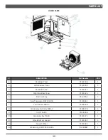
Page 32: ...base panel INOX P113568B 1 7 Front base panel INOX P113569M 1 8 Right side base panel INOX P113570G 1 9 Adjustable feet support 40X40 SP 1 5 M10 P113571E 2 10 Adjustable feet TH40 M10X65 P113572C 2 11 Support Whell Ø80 fi xed P113573A 2 12 Compressor Unit Assembly P116621E 1 NOTE The Condensing unit relay will differ based on the serial number of the MIDA case If the MIDA case serial number ends i...

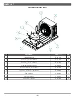
Page 33: ...densing Fan Motor MIDA 4 P113575G 1 3 Condensing Fan Blade MIDA 4 P116622C 1 4 Condensor Fan Guard MIDA 4 P116623A 1 5 Compressor Start Capacitor MIDA 4 P116624K 1 6 Compressor Start Relay ePTC MIDA 4 P116625G 1 7 Clikson MIDA 4 P116627C 1 8 Filter Dryer MIDA 4 P116629K 1 9 Condensor Coil MIDA 4 P116631D 1 ...

Page 34: ... BLANK 32 PARTS LIST ELECTRICAL CORD DESCRIPTION Part Number PCS 1 Electrical plug NEMA 5 15 Straight Blade Plug P113636D 1 Electrical plug NEMA L5 15 Locking Plug P117255A 1 ...

Page 35: ...nt Rear close panel INOX P113577C 2 2 Joining kit P113578A 1 3 Cables profile P113579K 1 4 Case Controller MIDA 8 P116633M 1 P116633M 1 5 Temp Sensor MIDA 8 P116634H 1 6 Anti Fog Front Double P117551C 1 NOTE All parts on MIDA 8 same as MIDA 4 parts unless shown on this page ...

Page 36: ... BLANK 34 PARTS LIST MIDA 4x4 MIDA 4x8 PARTS ORDERING NOTES ...

Page 37: ...ng information about the part you are ordering Model number and serial number of the case for which the part is intended Length of the part if applicable Color of part if painted or color of polymer part Whether part is for left or right hand application Quantity ...

Page 38: ... BLANK 36 PARTS LIST END WALLS SIDE BUMPER DESCRIPTION Part Number PCS 1 Label Load limit line P114171B 1 2 Plexiglass end wall P114172M 1 3 End wall bumper rail kit P114173H 1 ...

Page 39: ... SX P114146E 4 2 Plexi Worktop P114147C 2 3 Honeycomb P114148A 1 4 Honeycomb Holder P114149K 1 5 Front Rear Glass P114150F 2 6 Rear Closed Air Inlet P114151D 1 7 Product Holder P114152B 1 8 Front Holed Air Inlet P114153M 1 9 Front Air Inlet P114154H 1 10 Front and Back Bumper Rail Kit P114155F 2 ...

Page 40: ...ARTS LIST EVAPORATOR EVAPORATOR FANS DESCRIPTION Part Number PCS 1 Evaporator R290 P114156D 1 2 Protective Metal Grid For Evaporator Fan P113562D 1 3 Evaporator Fan Complete with Impeller and Metal Ring P113563B 1 ...

Page 41: ... 1 4 Right Side Base Panel P114162A 1 5 Electrical Plug P113576E 1 6 Carel Thermostat PJEZCOH100 P113566F 1 7 Temp Sensor MIDA 3 P116632B 1 8 Condensing Unit Relay MIDA 3 P116637B 1 9 On Off Switch P113565H 1 10 Adjustable Feet TH40 P114167A 1 11 Adjustable Feet Support P114166C 1 12 Support Wheel P114168K 1 13 Condensing Unit SP 0905 083A P115686M 1 ...

Page 42: ... Condensing Fan Motor MIDA 3 P114169G 1 3 Condensing Fan Blade MIDA 3 P116622G 1 4 Condensor Fan Guard MIDA 3 P116623A 1 5 Compressor Start Capacitor MIDA 3 P116624K 1 6 Compressor Start Relay ePTC MIDA 3 P116626E 1 7 Clikson MIDA 3 P116628A 1 8 Filter Dryer MIDA 3 P116630F 1 9 Condensor Coil MIDA 3 P116631D 1 ...

Page 43: ... BLANK 41 PARTS LIST MIDA 3X3 PARTS ORDERING NOTES ...

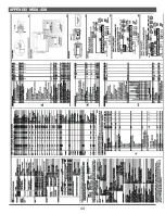
Page 44: ...42 APPENDIX MIDA 3X3 MIDA 4X4 ...

Page 45: ......

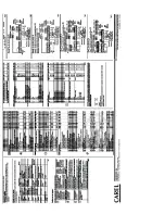
Page 46: ...44 APPENDIX MIDA 4X8 ...

Page 47: ......

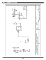
Page 48: ...46 MIDA 3X3 WIRING DIAGRAM ...

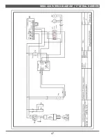
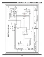
Page 49: ...47 MIDA 4X4 WIRING DIAGRAM C SERIAL NUMBER ...

Page 50: ...l 16 05 2022 Date Operating voltage System Category Frequency Power plug features PE connection types components 120 Volt L N 60 HZ Component CLASS 5 1 1 3 Paper Nr 01 M M01 R01 T01 T 1 1 7 7 R02 S01 A1 A2 1 2 3 4 5 6 13 14 21 22 K01 110Vac L N E01 M M03 2 2 M M02 L N 5 RED RED sd01 sd02 9 2 3 4 11 7 8 10 PJEZC0H100 5 8A 2FLA 12LRA 6 1 L N AMB T DEF T DI PROBE L 8 4 A 12A 10FLA 60LRA 10 10 A 115 V...

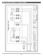
Page 51: ... BLANK 49 MIDA 4X8 WIRING DIAGRAM C SERIAL NUMBER ...

Page 52: ... BLANK 50 MIDA 4X8 WIRING DIAGRAM C SERIAL NUMBER ...

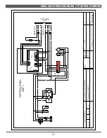
Page 53: ... Frequency Power plug features PE connection types components 120 Volt L N 60 Hz Componenti CLASSE 5 1 1 3 Paper Nr 01 ELETRICAL PANEL UNIT 1 M M01 R01 T01 T 3 3 2 2 R02 S01 L N 110 240 Vac NO4 IJFPSA4B06S0060 GND 0 10V NO3 C1 NO1 NO2 GND sd01 sd02 VCC BMS A1 A2 1 2 3 4 5 6 13 14 21 22 K01 110Vac L N Dl1 Dl2 GND S1 S2 E01 M M03 1 1 M M04 L N P01 Cable A 4x1 5 TO TERMIANAL BOX 2 Cable B 4x1 5 B2 B3...

Page 54: ...52 MIDA 4X8 WIRING DIAGRAM D SERIAL NUMBER ...

Page 55: ...eshold Deviation 0 0 A4 Digital input configuration 10 10 Ac High Condenser Temperature Alarm 60 140 AE High Condenser Temperature Alarm Differential 5 4 Acd High condenser temperature alarm delay min 0 5 Ad Low and high temperature alarm delay 0 5 FAN PARAMETERS DEFAULT ACTUAL F0 Fan Management 0 0 F1 Fan Shutdown Temperature 5 60 F2 Fans Off When Compressor Off 1 0 F3 Fans Status During Defrost ...

Page 56: ...54 ...

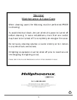
Page 57: ...r water directly on fan motors or any electrical connections All lighting receptacles must be dried off prior to insertion and re energizing the lighting circuit Please refer to the Use and Maintenance section of this installation manual 1925 Ruffin Mill Rd Colonial Heights VA 23834 Due to our commitment to continuous improvement all specifications are subject to change without notice Hillphoenix ...

Page 58: ...nstallation and startup forms are not properly completed or returned within two weeks after startup 5 If the defective part is not returned to the Manufacturer 6 To service maintenance or wear and tear parts such as lights starters and ballasts MODIFICATIONS TO GENERAL WARRANTY The following sets forth certain modifications to the General Warranty for specific products of Manufacturer DISPLAY CASE...

Reviews: