L1 NON-INSULATED PARTITION INSTALLATION INSTRUCTIONS
Non
Insulated
Partition
Installation
Instructions
Use
the
following
instructions
to
install
Hillphoenix
non
insulated
partitions.
It
is
recommended
that
all
shelves
and
deck
pans
from
both
sides
of
the
partition
be
removed
to
avoid
any
potential
damage
or
injury.
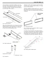
Step
1
:
Mount
the
two
vertical
retainer
brackets
to
the
shelf
standard
(figures
1
&
2)
using
the
supplied
tek
screws
(8
‐
18x3/4).
The
rectangular
cutouts
in
the
retainers
must
align
with
the
rectangular
slots
in
the
shelf
standard.
Vertical
Retainer
Bracket
#1
should
be
located
below
the
3
rd
slot
from
the
top
and
Vertical
Bracket
#2
should
be
located
above
the
6
th
slot
from
the
bottom.
The
grooves
in
the
vertical
retainer
brackets
must
be
centered
on
the
case
to
case
joint.
The
tek
screws
are
to
be
drilled
through
the
pre
‐
drilled
holes
in
the
retainer
brackets
as
shown
in
figure
3.
Note
that
the
vertical
and
horizontal
retainer
brackets
are
identical.
Step
2:
Slide
the
Plexiglas
partition
into
the
vertical
retainer
brackets.
Use
the
supplied
retainer
bolts
and
nuts
(8
‐
32x1/2)
to
secure
the
Plexiglas
partition
to
the
vertical
retainer
brackets
as
shown
in
figure
3.
Drill
additional
holes
in
the
Plexiglas
if
the
pre
‐
drilled
holes
in
the
Plexiglas
do
not
line
up
with
the
holes
in
the
retainer
brackets.
Step
3:
Slide
Horizontal
Retainer
Bracket
#2
onto
the
bottom
of
the
Plexiglas
partition
as
shown
in
figure
2.
Align
the
partition
parallel
to
the
pipe
chase
and
secure
the
bracket
by
drilling
directly
into
the
pipe
chase
using
the
supplied
tek
screws.
Slide
Horizontal
Retainer
Bracket
#1
onto
the
top
of
the
Plexiglas
partition
and
secure
it
to
the
top
flue
of
the
case
using
the
supplied
tek
screws.
Secure
the
partition
using
the
retainer
bolts
and
nuts
in
the
horizontal
retainer
brackets
as
done
in
step
2.
Figure
1:
Top
of
Plexiglas
Partition
Figure
2:
Bottom
of
Plexiglas
Figure
3:
Vertical
Retainer
Bracket
Installation
Summary of Contents for Hillphoenix ONRZ
Page 23: ...ELECTRIC DEFROST 1 PHASE E2 ELECTRICAL WIRING ...
Page 24: ...E3 ELECTRIC DEFROST 3 PHASE ELECTRICAL WIRING ...
Page 25: ...E4 ELECTRIC DEFROST HOT GAS ELECTRICAL WIRING ...
Page 31: ...J2 SEISMIC BRACKETS 5 BRACKETS ...
Page 32: ...J3 SEISMIC BRACKETS 7 BRACKETS ...
Page 33: ...J4 SEISMIC BRACKETS 11 BRACKETS ...


