ELECTRONIC DISPLAY MODULES M1
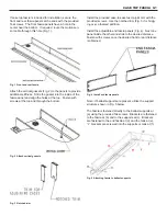
The electronic display module (EDM) is installed within a
protective enclosure (Fig. 1) and is initially secured to the
top-rear area of the case. Unscrew the display module
from this location.
Pull the display module forward to the front, left-hand side
of the case. If top fascia is utilized, slide the display mod-
ule through the pre-cut rectangular hole in the fascia (Fig.
2) until it sits flush against the cornice.
Fig. 1 Electronic display module inside protective enclosure
Fig. 2 Slide EDM through pre-cut hole in fascia
Align the pre-drilled holes in the display module and the
fascia (Fig. 3), then secure the module using the provided
screws.
NOTE: these instructions do not apply to Airewave fascia.
If top fascia is not included, align the front of the display
module flush to the front of the cornice (Fig. 4), locating
the left edge of the display module 9.25” from the left end
of the case. Secure the display module by drilling two
screws into the top canopy.
Fig. 3 Align with pre-cut holes and secure with screws
Fig. 4 Align with cornice front and secure with screws
Summary of Contents for Hillphoenix ONRZ
Page 23: ...ELECTRIC DEFROST 1 PHASE E2 ELECTRICAL WIRING ...
Page 24: ...E3 ELECTRIC DEFROST 3 PHASE ELECTRICAL WIRING ...
Page 25: ...E4 ELECTRIC DEFROST HOT GAS ELECTRICAL WIRING ...
Page 31: ...J2 SEISMIC BRACKETS 5 BRACKETS ...
Page 32: ...J3 SEISMIC BRACKETS 7 BRACKETS ...
Page 33: ...J4 SEISMIC BRACKETS 11 BRACKETS ...


