


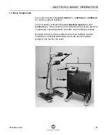

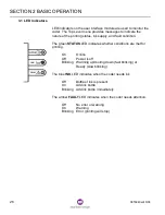


SECTION 2 BASIC OPERATION
0855849enf 6/08
27
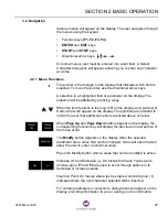
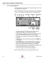
3.2 Navigation
Various menus will appear on the display. The user navigates through
the menus using the keypad.
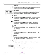
•
Function keys (F1, F2, F3, F4)
•
ENTER and EXIT keys
•
START and STOP keys
•
Directional arrow keys
On some menus, text must be entered into a text field. A Select
Character dialog box will appear, allowing you to enter one character
at a time.
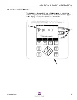
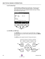
3.2.1 Menu Functions
The pointer is the triangle on the display that indicates which field is
selected. To move the pointer, use the directional arrow keys.
A selection is a highlighted field or parameter on the display. The
selection will be affected by pressing a key.
When the list of options is too long to fit on the display, an Up-Arrow or
Down-Arrow will appear on the display. The symbols are intended to
inform the user that additional options are listed above or below.
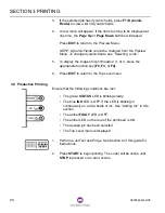
When Page Up and Page Down buttons appear on the display, the
corresponding function key will display the previous or next portion of
the menu or list.
The Modify button appears on the display when the selected
parameter has a value that can be changed. A box will open that will
allow the user to enter a numerical value.
Press the Modify button when a value that can be modified is active.
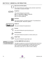
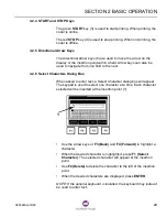
Increase (+) and Decrease (–): On menus that have + (plus) and -
(minus) signs, F1 and F2 are used to scroll through options or to
decrease or increase values.
Insertion Point: On menus where text is entered, a blinking line ( I )
indicates where the next character selected will be inserted.
For certain parameters or selections, dialog boxes will appear on the
display, providing information to you or asking you for information.
Summary of Contents for Markem-Imaje 5000 Series
Page 1: ...o p e r a t i o n g u i d e ...
Page 2: ......
Page 4: ...iv 0855849enf 6 08 ...
Page 7: ...Model 5200 5400 Operation Guide SECTION 1 General Information ...
Page 8: ......
Page 18: ...SECTION 1 GENERAL INFORMATION 12 0855849enf 6 08 FRONT REAR ...
Page 24: ......
Page 25: ...Model 5200 5400 Operation Guide SECTION 2 Basic Operation ...
Page 26: ......
Page 38: ......
Page 39: ...Model 5200 5400 Operation Guide SECTION 3 Printing ...
Page 40: ......
Page 55: ...Model 5200 5400 Operation Guide SECTION 4 Cleaning and Care ...
Page 56: ......
Page 61: ...Model 5200 5400 Operation Guide SECTION 5 Troubleshooting ...
Page 62: ......
Page 67: ...User Documentation Department ...


