


SECTION 2 BASIC OPERATION
0855849enf 6/08
31
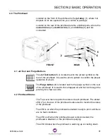
4.0 The Printhead
Located on the front of the printhead is the jet array (1), where hot
droplets of ink are ejected onto your carton or package.
Located on the rear of the printhead are the umbilical ports, where the
vacuum lines (2), electrical line (3), and ink line (4) and are
connected.
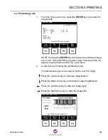
4.1 Jet Test and Purge Buttons
The Jet Test button (5) is located next to the jet test symbol on the
rear of the printhead. It is used to print a pattern to confirm the proper
operation of all jets.
The Purge button (6) is located next to the purge symbol on the rear
of the printhead. It is used to force trapped air and hot ink through the
jet array for a few seconds.
4.2 Printhead Status
The Top Level menu reports the status of each printhead. The amber
LED (7) on the rear of the printhead is also used to monitor the status
of the printhead.
The LED is on when the printhead is enabled, ready to print, and there
are no fault conditions.
The LED is off when the printhead power is disconnected, the
printhead is disabled, or the printhead is purging.
The LED blinks when the printhead is warming up or cooling down.
REAR
FRONT
1
3
2
4
5
6
7
Summary of Contents for Markem-Imaje 5000 Series
Page 1: ...o p e r a t i o n g u i d e ...
Page 2: ......
Page 4: ...iv 0855849enf 6 08 ...
Page 7: ...Model 5200 5400 Operation Guide SECTION 1 General Information ...
Page 8: ......
Page 18: ...SECTION 1 GENERAL INFORMATION 12 0855849enf 6 08 FRONT REAR ...
Page 24: ......
Page 25: ...Model 5200 5400 Operation Guide SECTION 2 Basic Operation ...
Page 26: ......
Page 38: ......
Page 39: ...Model 5200 5400 Operation Guide SECTION 3 Printing ...
Page 40: ......
Page 55: ...Model 5200 5400 Operation Guide SECTION 4 Cleaning and Care ...
Page 56: ......
Page 61: ...Model 5200 5400 Operation Guide SECTION 5 Troubleshooting ...
Page 62: ......
Page 67: ...User Documentation Department ...


