background image

MG586 Introduction 

W450030A 09/09

Operator’s Display Console

Warning/Alarm Indicators

The red two-block lamp will illuminate when a two-
block condition occurs. 

The yellow pre-warning lamp will illuminate at 90% of 
rated capacity. 

When the load reaches or exceeds 100% of rated 
capacity, the red overload warning lamp will 
illuminate along with the yellow pre-warning lamp, 
when this occurs, the computer will implement a 
function kick-out, which in turn, disables the boom 
down, winch up, and extend out functions.   

Display Windows

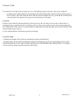
The current rated capacity for the crane in the current configuration will be displayed in the rated capacity 
window as well as the percent of rated capacity shown as a meter which progresses to the right as the load 
increases. Refer to “Normal Operation” Section of this manual.

The setup codes have been pre-configured to match the setup of the crane.  The setup codes are shown as 
well as the parts-of-line. Refer to “Configuration Selection” Section of this manual. 

The information window shows crane specific information regarding boom length, boom angle, and working 
radius, along with the load on hook. In addition, information regarding any warnings or alarms will be 
displayed in this window. If the system has any internal faults, it will display “!WARNING! SYSTEM FAULT” in the 
information window. The specific fault messages can be viewed by pressing the 

83$552:

 or 

'2:1$552:


key. Refer to “System Fault Messages” Section of this manual.

5DWHG&DSDFLW\

6HWXS&RGH

,QIRUPDWLRQ

W450030r2 03/16

Summary of Contents for MG586

Page 1: ...MicroGuard 586 Rated Capacity Indicator System for Truck Mounted Cranes Miller Operation Setup Maintenance ...

Page 2: ......

Page 3: ...W450030r2 03 16 ...

Page 4: ...is knowledgeable in safety guidelines crane capacity information and the crane manufacturer s specifications This manual describes operation setup and troubleshooting procedures for the system Please make sure to read understand and follow the contents and instructions contained within this manual By doing so the operator will have a more clear indication of rated capacity approach to overload and...

Page 5: ...e system includes a computer an operator s display console an extension reel and various types of electrical cables and sensors and is designed to measure and display load weight calculate and display maximum capacity percentage of rated capability crane configuration numbers parts of line and warn of an approaching overload or two block condition for each crane configuration W450030r2 03 16 ...

Page 6: ...rovides a path from boom head to the computer by way of the extension reel cable This path is used to send a two block signal to the computer The operator s LVSOD RQVROH translates data received from the computer and displays the actual load weight and percent of rated capability in the display windows Visual and audible warning alarms activate when capability limits are approaching or exceeded or...

Page 7: ... as the percent of rated capacity shown as a meter which progresses to the right as the load increases Refer to Normal Operation Section of this manual The setup codes have been pre configured to match the setup of the crane The setup codes are shown as well as the parts of line Refer to Configuration Selection Section of this manual The information window shows crane specific information regardin...

Page 8: ...le the audible warning and to override the function kick out for the current alarm condition The boom will continue to move as long as the button is on hold after the reset To reconnect the function kick out simply allow the button to return The CONTRAST keys are used to adjust the lightness or darkness of the display area The DISPLAY MODE SELECT keys are used to switch to different display format...

Page 9: ...now show Miller MR3 and capacity chart numbers 2916 2917 for the System The setup code window will display the same setup code used when the system was last powered off Check that the correct setup code is displayed before operating the crane The first selection will be blinking 1 and is the only available boom selection Pressing the setup key will go to the next selection Parts of Line as in the ...

Page 10: ...ration selection allows for jib selection Since there are no jib options for this model the system defaults to the main boom Main Boom 6HWXS 2 RQWUDVW LVSOD 0RGH 6HOHFW ODUP 2YHUULGH Press the 6 783 2 key to continue The current number of parts of line is now flashing To change the parts of line press the 83 552 or 2 1 552 key to select the desired number and press the 6 783 2 key to continue W450...

Page 11: ...WARNING AT ALL TIMES OBSERVE SAFE PRACTICES MAKE SURE THAT CRANE CAPACITY LIMITATIONS ARE UNDERSTOOD AND THAT THE CRANE CAPACITY PLATE IS FOLLOWED DO NOT EXCEED MANUFACTURER S SPECIFIED LIFTING LIMITATIONS Recommended Tools Phillips Screwdrivers Digital Level Accurate to 0 1 at level Digital Voltmeter Measuring tape at least 100 feet 200 feet preferable fiber type in tenths of feet Crane Configura...

Page 12: ...arrow on the display for 5 10 seconds at any time to start the self test 2 The setup screen should appear as in the graphic below when the calibration mode is complete 3 Boom Angle Zero Fully retract the main boom and use an inclinometer or accurate bubble level to ensure the boom is completely level 4 Ensure that the inclinometer reading is made on the top flat surface of the boom Take several re...

Page 13: ...amp is applied to the cable Boom Length Zero and Span Function After completion of the angle 0 functions the MG586 will display the screen below for Extension Zero NOTE The value beside the Exten 0 0 should equal 0 2 if the reading is correct remove the cogbelt and rotate the sensor clockwise until it hits the clutch stop If the reading is incorrect move the pulley counterclockwise exactly one tur...

Page 14: ...hysical radius measurement and compare the measurement to the MG586 display 1RWH 5DGLXV LV DOORZHG WR EH GLVSOD HG ORQJ E IRRW EXW VKRXOG QRW GLVSOD VKRUW Presss the UP arrow to select the Angle Span screen Set the boom elevation to exactly 60 using the digital level While the display in the Angle Span mode pressing the setup button will cause the system to span the angle at exactly 60 Pressing th...

Page 15: ...tension reel houses the reel off cable to the boom tip a cable from the extension reel to the computer and the boom angle sensor The extension reel provides the following signals that are sent directly to the computer via the extension reel computer cable The Boom Extension Signal is generated within the extension reel and controlled by the reel off cable as the boom is extended or retracted The e...

Page 16: ...to the computer cable in the extension reel Check the following Carefully examine the reel off cable for damage Fully telescope the boom in and out As you extend or retract the boom ensure that the reel off cable is smoothly fed on and off the extension reel without drooping along the boom or jumping especially as the boom is retacted WARNING THE EXTENSION REEL SETTING IS FACTORY PRESET IF THE REE...

Page 17: ...llation Section of this manual Checking the Two block Warning Signals and Cutout of Machine Motions The following test activates the anti two block warning signals and the valve controlling cut out of crane motions to ensure proper operation No other pre existing alarm conditions may be active when performing this test WARNING Before performing this test turn the crane power off and then on again ...

Page 18: ... of all of the sensors in the system and the correct code number setting for the configuration of the crane If no stowed deduct configuration is provided by the system perform this test with stowed attachments removed It is recommended that a load test be performed monthly Load Test Steps Calculate the weight of the total load including the slings and hook block Lift the weight and record the load...

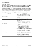
Page 19: ...orrective Action Reselect Crane Setup This message indicates that there is an error in the crane setup selection or there is an internal computer fault Reselect the correct crane setup code the error should correct itself If not replace the computer Refer to Computer Replacement page 2 Check Extension This message indicates a problem with the boom extension sensor 1 Inspect check cabling and conne...

Page 20: ...gnals for the two block drive and signal within the extension reel Refer to Extension Reel Voltage Checks page Check FKO This message indicates a Function Kick Out wiring problem that is usually caused by a fuse or crane circuit breaker failure Remove the computer unit lid and check the 10A fuse Replace the Computer This message indicates an internal fault in the computer In some cases it may not ...

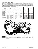
Page 21: ...VE 4 7V 5 3V TB1 4 RED TB1 1 BLUE ANGLE SENSOR OUTPUT 0 degrees 0 4V 0 6V TB1 2 GREEN TB1 1 BLUE EXTENSION SENSOR OUTPUT 0 ft 0m FULL RETRACTED 0 15V 0 35V TB1 3 WHITE TB1 1 BLUE TWO BLOCK DRIVE ATB WEIGHT DOWN 5 5V 7 5V TB1 6 BLACK TB1 1 BLUE ATB WEIGHT UP 9 5V 10 5V TB1 6 BLACK TB1 1 BLUE TWI BLOCK SIGNAL ATB WEIGHT DOWN 5 5V 7 5V TB1 5 BROWN TB1 1 BLUE ATB WEIGHT UP 0V 2V TB1 5 BROWN TB1 1 BLUE...

Page 22: ...d three communications indicators D7 D9 and D12 all Indicators are bright green light emitting diodes With the exception of the communications indicators all indicators should be illuminated at the same brightness level with the system power on A missing or dimly lit indicator indicates a power supply problem LED Indicator Function D7 Communication Indicator TST0 D8 Battery Power_POS D9 Communicat...

Page 23: ...he differences in computer unit configurations the locations of these indicators may vary as shown below LED Indicator Function D7 Communication Indicator TST0 D8 Battery Power_POS D9 Communication Indicator TST1 D10 VP D11 10V D12 COMM Communications Indicator D13 8V2 D14 5V D17 3V3 W450030r2 03 16 ...

Page 24: ... install a new computer unit 1 Mount the computer unit Ensure that all electrical power is turned off Connect all electrical connectors to the computer unit ConneDU hydraulic hoses to the computer pressure poSUs Green is base side and red is rod side of the boom hoist cylinder If more than one fault is present the most serious fault will appear first and must be resolved first When the first fault...

Page 25: ...ATB Cable Replacement for A240700 Reel Assembly ...

Page 26: ...SLIP RING W450030r2 03 16 ...

Page 27: ...W450030r2 03 16 ...

Page 28: ...SLIP RING W450030r2 03 16 ...

Page 29: ...W450030r2 03 16 ...

Page 30: ...37 Phone 918 298 8300 Fax 918 298 8301 www dovertwg com As a leader in product innovation TWG is committed to the ongoing improvement of its equipment We reserve the right to make changes to our products without notice 2020 TWG All rights reserved ...

Reviews: