21
62
60
59
56
2
94
81
54
61
57
69
58
67
55
64
95
66
66
65
BRAKE
PORT
67
53
52
50
68
16
If a complete tear down is not
necessary, make sure the
input shaft (21) does not
move during removal of the
drum. If the shaft is allowed
to move,
the input spacer
(104) will fall into the gear set
ultimately causing failure to
the gear section of the winch.
The gear cover (3) will have to
be removed to re-position the
spacer on the input shaft.
M. BRAKE SECTION ASSEMBLY
1. Re-assemble the driver/clutch assembly
making sure the clutch is installed properly
and checking to make sure the cam clutch is
free turning in the pay in direction.
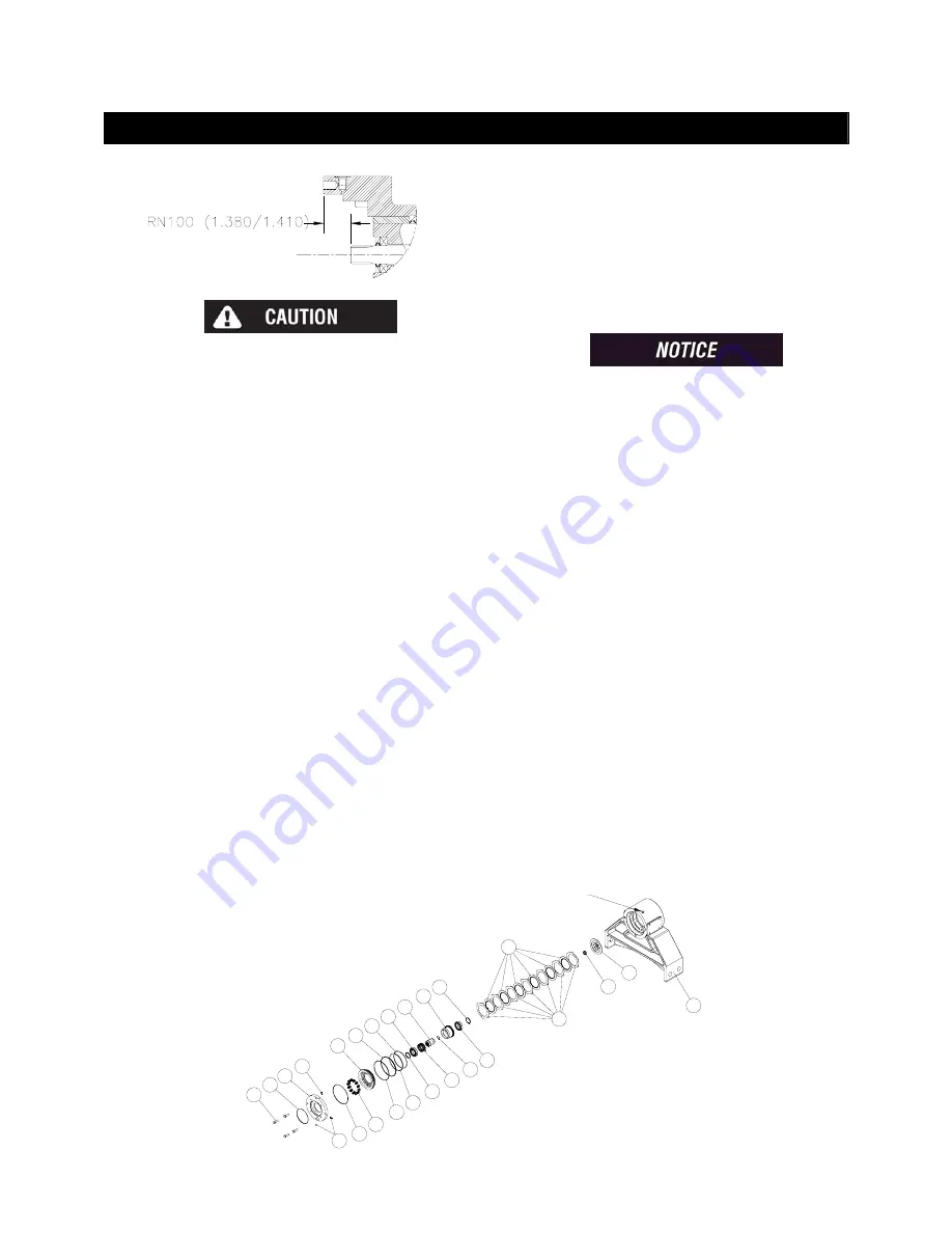
2. Measure the distance from the face of the
brake housing to the end of the shaft as
shown above.
3. If needed, add shims (113, 114) inside input
driver (64) on motor side to achieve
dimension shown above.
4. Install the bearing housing assembly that
contains parts 50 and 68 into the brake
housing.
5. Install the driver/clutch assembly onto the
input shaft (21).
6. Install the stator plates (52) and friction
discs (53) starting with a stator plate and
alternating between friction discs and stator
plates until seven stator plates and six
friction discs are used.
Dip friction discs in lightweight
Non-EP oil before installation.
7. Install the piston (54) into the brake housing
(16) and gently tap it down until it is seated
making sure not to damage the o-rings (55,
57) or back-up rings (56, 58).
8. Install the springs (59) into the spring
pockets. If working in a horizontal position,
coat the bottom of each spring with chassis
lube to keep it in position.
9. Install the cover (16) onto the brake housing
(16) using four cap screws (60). Draw the
cover down evenly, alternating between
opposite hex bolts. Make sure that the
cover is aligned properly with the brake
housing to orient the motor correctly.
10. Check the brake release with a portable
hydraulic pump. Full release should be
obtained at 340psi, plus or minus 20psi.
Also, check the brake for proper operation
by applying 107psi to the brake port and
adapting a torque wrench to the input shaft.
The torque in the payout should be 142 to
162 ft-lbs.
Summary of Contents for RUFNEK 100
Page 10: ...10 CLUTCH INSPECTION...
Page 27: ...27 VISCOSITY CHART...


