background image

Summary of Contents for Tipper Tie RS4203

Page 1: ...User Manual Model RS4203 Voiding Clipping Machine Manual Number 80 1382 Revision Number 32 January 11 2013 Copyright 2013 Tipper Tie Inc All rights reserved ...

Page 2: ...ntained This means that a preventive maintenance PM schedule should be established and followed Attention shall be given at least once a week to observing wear of all moving parts especially in the following areas The die gate and gathering gate channels and punch assembly Die and die pocket area of the die gate Knife or knife assembly Clip pusher assembly Conveyor and voider assemblies Operating ...

Page 3: ...ions 16 1 6 Major Components 17 Chapter 2 Safety Instructions 19 2 1 General Precautions 19 2 2 Safety Symbols 20 2 3 Disclaimer of Liability 20 2 4 Capital Equipment Safety Circuit Overview 21 2 5 Warnings and Cautions 21 2 6 Safety Illustrations 22 Chapter 3 Delivery and Setup 27 3 1 Delivery 27 3 2 Unpacking Equipment 27 3 3 Main Circuit Breaker 28 3 4 Stuffer Connection 28 Chapter 4 Air Connec...

Page 4: ...ol 35 5 4 Touch Screen 36 Chapter 6 Machine Operation 37 6 1 Preparation 37 6 2 Starting the Machine 37 6 3 Loading Clips Stick Clips 39 6 4 Loading Clips Reel Clips 40 Chapter 7 Recipe Descriptions 43 Chapter 8 Touch Screen 49 8 1 Run Screen 49 8 2 Home Screen 50 8 3 Recipe Screen 51 8 4 Calibrate screen 52 8 5 Sequence Screen 53 8 6 Input Screens 54 8 7 Output Screens 55 8 8 Help Screens 56 8 9 ...

Page 5: ... Loops on the Looper 67 10 8 2 Looper Settings and Adjustments 69 Chapter 11 Conveyor Assembly Operation and Adjustments 75 11 1 Conveyor Assembly Layout 75 11 2 Conveyor Air Motor 75 11 3 Air Motor Speed Controls 75 11 4 Lubrication 75 11 5 Trip Paddle 76 Chapter 12 Programmable Controller 77 12 1 Description 77 12 2 Memory Cassette 77 12 3 Battery Replacement 78 Chapter 13 Cleaning Procedures 81...

Page 6: ...nual Preventive Maintenance 101 14 12 Annual Preventive Maintenance 103 Chapter 15 Troubleshooting Guide 105 Chapter 16 Troubleshooting by Product Appearance 107 Chapter 17 Spare Parts Lists 111 Chapter 18 Assembly Drawings 113 18 1 RS4203 Main Assembly and Clippers 113 18 2 Installation Kit and Spare Parts Kits 113 18 3 Frame Base Air Prep and Valving 113 18 4 Controls 114 18 5 Horns Skin Brakes ...

Page 7: ...ox Added cautions to avoid high pressure cleaning and use of abrasive cleaners on touchscreen and glass Updated several drawings March 7 2005 14 01 Updated manual to match recent equipment changes including new photos illustrations Incorporated extensive engineering reviews Updated drawings from recent ECNs April 20 2005 14 01 Translation to Swedish April 2005 15 Added Liability Disclaimer page an...

Page 8: ...otor 00 2877 and the alternate water separator filter element in Spare Parts Lists Updated ECN drawings January 17 2010 25 Changed cover logo address contact box and high air pressure symbol Updated ECN drawings July 20 2010 26 Formatted for double sided printing August 11 2010 27 Replaced corporate logo Changed proximity sensor maintenance step to an inspection Updated ECN drawings November 1 201...

Page 9: ...ssories Any declaration made under this warranty must be presented in writing to Tipper Tie during the Warranty Period 1 C Tipper Tie Inc will not be liable for personal injury or property damage nor shall it have obligations or liabilities for consequential damages including but not limited to product loss film loss and lost profits even if advised of the possibility of such THE FOREGOING WARRANT...

Page 10: ...ver associated with the Product shall be assumed by Customer If any of the provisions of this agreement are invalid under any applicable statute or rule of law they are to that extent deemed omitted The Customer s remedies in this agreement are exclusive Any purchase order or similar form attached hereto is void to the extent that it contains any terms that are contrary to or inconsistent with the...

Page 11: ...n through which the operator can easily set and change operating parameters and which provides automatic machine diagnostics for machine status and troubleshooting The system is operator friendly and very reliable 1 2 Operation The RS4203 has an easy to use interface display unit or touchscreen which provides a simple and useful means of communication between the operator and the machine s process...

Page 12: ...of operation The RS4203 operating specifications are as follows The machine produces packages that are air free with clean tails The RS4203 is low maintenance easy to clean and meets all USDA and CE safety and sanitation standards It handles all hard and soft emulsion products plus chunk section and formed products One operator can produce up to 24 packages per minute depending on the type of prod...

Page 13: ...n data and specifications and is similar to the one shown below The RS4203 is available in low voltage 115 VAC or high voltage 230 VAC versions The following name plate is for the low voltage RS4203 Model Machine Family Serial Number Production Date Machine Weight Max Allowable Air Pressure Pneumatic Schematic Number Rated Voltage and Phase Frequency Rated current of the machine including multiple...

Page 14: ...rrent consumption of largest motor Max Allowable fuse size for normal overcurrent protection Overall Short Circuit Current Rating Electrical Schematic Number Power consumed by the machine in KVA or Watts Note The 230 volt version does not include a heater fan combination Additional Specifications Electric control box heater 115 VAC 100 watt 50 60 Hz Note Check the voltage requirements of the heate...

Page 15: ...troller PLC source input and source output PLC o Mitsubishi FX2NC 32MT DSS Base Module o 1 FX2NC 16EX DS Extension Module Input o 2 FX2NC 16EYT DSS Extension Module Output Machines built or upgraded after Feb 21 2011 will use a Mitsubishi FX3UC 32MT DSS PLC Note The FX2NC input and output modules are compatible with the FX3UC PLC Machines built or upgraded after Feb 21 2011 will use a CTC PA2 Touc...

Page 16: ...and Specifications Rev 32 01 11 13 Copyright 2013 Tipper Tie Inc All rights reserved 16 1 5 Layout and Dimensions Machine weight 1 220 pounds 553 4 Kg Shipping weight 1 700 pounds 771 1 Kg 33 inches 83 8 cm 120 inches 304 8 cm 68 inches 172 7 cm ...

Page 17: ...clips Operator Interface Panel Horn Rotor Mount Assembly Horn Vacuum Assembly Skin Brake Flow Controls Guard Assembly Frame Assembly Clipper Air Quick Disconnect and Filter regulator Assembly 40 48 or 72 Conveyor Assembly Remote Station Looper Spool 1 6 Major Components The layout and major components of the RS4203 are shown in the following illustration ...

Page 18: ......

Page 19: ...s to the person in charge Do not modify remove discard disable or bypass guards or safety circuits All guards protective covers and shields must be in place before operating the machine Do not modify remove disable or bypass the guards Operating this machine with guards covers or shields removed could result in serious injury Prior to operating the clipper to ensure both personnel and product safe...

Page 20: ... Tipper Tie shall not be liable to any person for any defects or damages to persons or property resulting directly or indirectly from 1 any neglect misuse or abuse of the equipment including but not limited to improper or inadequate maintenance of the equipment or improper modification or alteration thereto or 2 any use of the equipment which contravenes any of the instructions set forth in this m...

Page 21: ...2 5 Warnings and Cautions When using this machine observe all instructions warnings and precautions Failure to comply could result in serious injury including cuts or crushed bones Warning Do not drill into or weld attachments on the frame of the machine Warning Do not modify remove disable discard or bypass guards or safety circuits Warning Do not operate the machine unless the safety circuit is ...

Page 22: ... emergency stop button which is located on the remote control panel Press the E Stop to immediately stop the machine E M E R G E N C YS TO P M A N U A LC LIP FE E DLO O P C TCP arker P O W E R O peratorInterface C Y C LE S TA R T S TO P LO A D R U N V oiderS huttle TO U C H SC R EEN and LO O P optional TOUCH SCREEN CYCLE START STOP MANUAL CLIP AND LOOP looper optional FEED LOOP optional LOAD RUN S...

Page 23: ...arge red knob Always turn off and lock out the electrical disconnect before performing any service or maintenance on the machine Note the danger label that warns against opening the control box in a wet location Also note the warning that turning off the main power switch does not remove all power from the control box To remove all electrical power from the control box disconnect the incoming elec...

Page 24: ...The machine s main air supply shut off and lock out valve red knob in the photo below is located alongside the air prep assembly underneath the conveyor on the outside of the electrical and pneumatic control box A quick disconnect shown on the right is provided for easy connection and removal of the incoming plant air supply Mechanical Lockout Required ...

Page 25: ... PUNCHDOWN PROXIMITY SWITCH CUT OFF KNIFE CYLINDER GATE ACTUATOR CYLINDER DIEASSEMBLY SAFETYINSTRUCTIONS Clipper Assembly KEEP ANDF CLEAR PUNC GATE PUNCH Keep hands fingers and clothes clear of the punch gate die and knife areas Punch down proximity switch Gate Actuator Cylinder Punch Cut off Knife Cylinder Die Assembly ...

Page 26: ...G VERYSHARP KNIFEEDGE KNIFE CYLINDER BRACKET KNIFE BLADE ASSEMBLY KNIFEBLADE KNIFEBLOCK KNIFECOVER KNIFEOPERATING AIRCYLINDER KNIFEASSEMBLY KNIFEBLADEASSEMBLY Knife block Knife blade Knife cover Warning Keep hands and fingers clear of cut off knife assembly Knife operating air cylinder Knife cylinder bracket Warning Very sharp knife edge Knife blade assembly Knife Blade Assembly Knife Assembly ...

Page 27: ...following materials with all correspondence Original bill of lading or a copy Vendor invoice or certified copy when claim is based on weight or when valuation of shipment has been improperly described Catalog pages or product information Original packing slip or receiving reports or a copy of the electronic bill of lading manifest 3 2 Unpacking Equipment For ease of shipping some components for th...

Page 28: ...ipper Tie Inc All rights reserved 28 3 3 Main Circuit Breaker When shipped the main circuit breaker in the control box is in the OFF position Turn the breaker ON 3 4 Stuffer Connection Connect the stuffer cable to the stuffer plug shown at right at the input end of the machine ...

Page 29: ... must be attached with the check valve half female to the supply side of the air circuit The factory air supply is connected to the machine using the quick disconnect shown on the right The incoming air is routed through the air supply shutoff and lock out valve with the red knob Use the shutoff and lock out valve to turn off the air supply before performing any service or maintenance 4 2 Air Prep...

Page 30: ...mended setting after cleaning Caution Do not use a polycarbonate bowl on the filter regulator A polycarbonate bowl may be damaged and could possibly fail if exposed to synthetic oils thinner solvents trichloroethylene kerosene and other aromatic hydrocarbons Therefore a metal bowl is required 4 5 Main Lubricator The main mechanical systems lubricator is mounted either on the back of the control bo...

Page 31: ...cribed for the main lubricator apply to the conveyor air motor lubricator The conveyor air motor lubricator uses SAE 10 pneumatic lubrication oil with a drop rate of one 1 drop for every 15 20 cycles 4 7 Voider Rotary Actuator Lubricator A separate lubricator shown below is also provided for the voider rotary actuator The lubricator is mounted below and to the right of the voider assembly The same...

Page 32: ......

Page 33: ... any changes that might occur in a particular product application Communication with the interface display unit is bi directional It not only requests and accepts information from the operator but also informs the operator of irregular conditions warnings and faults that can occur during operation An especially useful feature is the troubleshooting capability which is integrated in the programmabl...

Page 34: ...ptional LOAD RUN SKIN BRAKE SHUTTLE EMERGENCY STOP Control Panel Push the EMERGENCY STOP button to stop the machine immediately Twist the button clockwise to reset the machine for operation Note If the machine has push pull style E Stops pull the button out to reset the machine CYCLE START STOP Depress this button to begin the cycle Depressing during the cycle triggers completion of the current ma...

Page 35: ...he heat seal will start sealing film Once the heat seal is sealing film the green lights will illuminate If the heat seal is sealing film green lights ON and this button is pressed the heat seal will turn ON the Start Enable Clipper signal and start the fill clip process As an alternative to pressing the HS Start button twice to sync with the clipper i e once to start sealing and once to sync pres...

Page 36: ...grammable touch screen is the heart of the user interface and is used to set and change the machine s operating parameters to monitor machine operations and to assist in troubleshooting problems that may arise The following illustration shows an example of the Run Screen Refer to Chapter 8 Touch Screen for further details on touch screen operations ...

Page 37: ...e installed Pivot installed with all seals Horn installed Skin brake assembly installed Horn rotor aligned with skin brake assembly Fill tube connected to stuffer Filler cable installed End of casing switch reset Main air supply connected Electricity Connected Main electrical disconnect to ON position 6 2 Starting the Machine Complete the following steps in the order listed to start the machine 1 ...

Page 38: ...erating parameters to the desired values using the recipe screen The new parameters will not take effect until the SEND button on the recipe screen is pressed Refer to Section 8 3 for more information on using the recipe screen 8 Press the CYCLE START green button on the user interface panel to begin operation In the AUTO mode the stuffing and clipping cycle will automatically restart at the end o...

Page 39: ...tick clips are easily loaded for dispensing Clips are held in place within the clip rail and guided towards the punch by means of a clip weight Position the clips so that they slide down the rail and gently guide them down the rail Fit the clip weight so that it slides into the groove in the rail Gently slide it down the rail until it rests on the clips ...

Page 40: ...dder to load the clip reels Follow all safety procedures for proper ladder use Your Tipper Tie machine may employ some type of clip guide or channel to guide clips down to the clip rail To load clips properly gently guide them without pulling on the clips or exerting force on them through any channels or over any guide wheels or clip rollers First load the clip reel cardboard or plastic side down ...

Page 41: ...ey can go no further into the clipper The clips are now in place to be used for clipping A pawl on the clip rail helps feed the clips into the punch and prevents them from moving backwards To unload clips you must pull the pawl lever to release the clips Pinch the pawl together to allow the clips to move up the rail freely Turn the clip reel to take up the slack and gently guide the clips back up ...

Page 42: ......

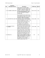
Page 43: ... knife cycle 1 100 1 3 PIECES SHIRR PIECES Used to enter the number of chubs expected from a shirr of casing This may be used instead of the end of casing trip lever 1 500 500 4 MULTI CUT CYCLES CYCLES An adjustable counter that sets the number of times the knife will extend during each clip cycle 1 10 1 5 MULTI PORTION COUNTS Counter which controls the number of portions desired from the filler p...

Page 44: ...eature ON or OFF FILL LAG COMPENSATE is used to send the start signal to the filler before the voider plates fully retract This allows the operator to adjust the point in the clip cycle when the product begins to flow The FILL LAG COMPENSATE time should initially be set at a large value and gradually decreased until the desired Filler start timing is reached On or Off Off 15 SKIN BRAKE FWRD ON OFF...

Page 45: ...The recipe item Conveyor Discharge Enable must also be set to ON On or Off Off 23 DISCHARGE EXTEND TIMER On machines equipped with a side discharge conveyor this option controls the amount of time the discharge paddles remain extended to fully eject the product from the conveyor The recipe item Conveyor Discharge Enable must be set to ON and Discharge Extended Lock must be set to OFF 0 20s to 5 00...

Page 46: ...parameter controls the amount of time the Start Filler output signal is OFF between multi portion fill cycles Value will depend on individual filler requirements Note When the Multi Portion Counts parameter is greater than 1 some fillers require the RS4203 s Start Filler output to turn off and back on to allow the filler to pump again 0 00s to 1 00s 0 00s 32 SKIN BRAKE DELAY SEC A timer which cont...

Page 47: ...utive portions Note a portion in this case is defined as cut to cut and may consist of several chubs i e the conveyor stays on low between chubs until the chub count is reached 0 00s to 2 00s 0 70s 39 FILL DELAY AFTER TANDEM An adjustable timer controlling the amount of time to delay the start of the fill cycle when running in tandem mode The time delay begins when the tandem machine completes its...

Page 48: ......

Page 49: ...eration button RESET SHIRR COUNT Can be used to reset the shirr count during cycles when the casing is longer than the original shirr count setting RESET CYCLE COUNT Resets the cycle counter AUTO MODE PRESS FOR MANUAL Press this button to change from continuous machine operation to the manual mode for running one piece at a time In the MANUAL mode the CYCLE START button must be pressed at the begi...

Page 50: ...RUN RECIPE and SEQ sequence screens the PLC error screen the KEYENCE calibration screen and the CHANGE USER module It also provides the jog filler button and displays the total machine cycles The part number of the operator interface software as well as the part number of the software currently installed in the PLC is displayed on this screen as shown in the lower right of the illustration ...

Page 51: ...ard and press ENTER The SAVE LIST button on the main recipe screen toggles to read press to save values Press it to save your new values Note The SAVE LIST button may be password protected to prevent unauthorized modification of recipes If only an ON OFF parameter is to be changed pressing the EDIT key changes the state of the parameter After all of your new recipe values have been edited and save...

Page 52: ...ved 52 8 4 Calibrate screen The calibrate screen is used to record and store background and target data for registration I marks Background target data for up to eight different color combinations may be recorded and stored for future recall This screen is available only with the Registration option ...

Page 53: ...quence screen displays a fault message in place of the step indicator Press the fault message to access additional information related to the cause of the fault The reason for the fault will be highlighted in red on the fault message Also available on this screen is the single step mode which will allow the machine to proceed by one step at a time each time the CYCLE START STOP pushbutton is press...

Page 54: ...RS4203 Manual Chapter 8 Touch Screen Rev 32 01 11 13 Copyright 2013 Tipper Tie Inc All rights reserved 54 8 6 Input Screens The input screens indicate the current state of all inputs ...

Page 55: ...RS4203 Manual Chapter 8 Touch Screen Rev 32 01 11 13 Copyright 2013 Tipper Tie Inc All rights reserved 55 8 7 Output Screens The OUTPUT screens indicate the current state of all outputs ...

Page 56: ...rights reserved 56 8 8 Help Screens The RS4203 user interface provides item specific HELP screens for many of the touch screen functions Press the HELP button on any screen to access additional information about that screen The sequence help screen and the PLC error help screen are shown ...

Page 57: ... be accessed from any of the OUTPUT screens allows a technician to directly control the machine s outputs and is intended for use only by Tipper Tie technicians Caution The output test mode disables all software inhibited outputs i e any output may be activated regardless of the potential for interference between mechanical components This function is password protected ...

Page 58: ......

Page 59: ... 32 01 11 13 Copyright 2013 Tipper Tie Inc All rights reserved 59 Chapter 9 Product Specification Worksheet A master copy of the product specification worksheet is included on the next page Use the master copy to make copies and use it to record recipe settings ...

Page 60: ...rake Lag On Off Registration On Off Pneumatic Filler On Off Stop Conveyor During Clip yes No Single Clip Between Chubs On Off Conveyor Discharge Enable On Off Discharge Extend Lock On Off Discharge Extend Time Seconds Discharge Sensor Type On Off Prod Present Gate Closed Dwell Seconds Punch Dwell Seconds Fill Lag Comp Seconds Portion Time Seconds Run On Delay Seconds Max Filler Timeout Seconds Res...

Page 61: ...e area do not attempt to cycle the machine again until the jam is cleared Follow all safety procedures Turn off the air supply and lock out the valve Carefully remove the clip or other obstruction from the die area so as not to damage the clipper parts 10 2 Clipper Operation The major components are shown in the illustration below Clipper operation is as follows Clipper swings down in between both...

Page 62: ...nts Rev 32 01 11 13 Copyright 2013 Tipper Tie Inc All rights reserved 62 10 3 Crimp Control Layout Refer to section 10 4 for details on adjusting the crimp control Clip rail Clip rail Punch down proximity switch Crimp control locking knob Rotate clockwise to lock knob ...

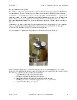
Page 63: ... the crimp control adjustment ring Before making an adjustment loosen the crimp control locking knob located at the far side of the support plate Rotate the crimp control adjustment ring clockwise to make a tighter crimp on the product Rotate the ring counterclockwise to make a looser crimp After the adjustments are complete retighten the crimp control locking knob Crimp control adjustment ring Ro...

Page 64: ...nd types Turn the T handle to adjust the pressure If the clip does not close properly after you have adjusted the crimp control ring and the punch pressure regulator check the incoming air supply pressure Also examine the punch and die for damage or accumulated dirt and debris that may be jammed into the die pockets The punch pressure regulator pressure gauge and T handle adjuster are shown below ...

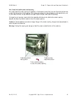
Page 65: ...ts to be run on the same machine Larger diameter casings require a larger closed position opening To adjust the iris opening loosen the voider adjustment locking knob Rotate the voider opening adjustment wheel counterclockwise to close the voider opening Caution A small adjustment produces a large change in the voider opening Always make adjustments in small measured increments Warning Closing the...

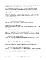
Page 66: ... position of the stop block which is adjustable The stop block has both coarse and fine adjustments Coarse adjustments are made by removing the slack fill coarse adjustment pin and moving the stop block along the series of position holes The position holes provide adjustment intervals of 0 75 inch 19 mm Fine adjustments are made by moving the position of the slack fill fine adjustment ring After t...

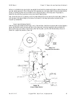
Page 67: ... tape The sections that follow provide instructions for adjusting the looper system Install the Loop Spool and Thread Loops Into the Looper Install the loop spool so that the loops come off the bottom of the spool and route the loops as shown in Detail H below Make sure the tape is fed between the Upper Loop Strip Plate and the Tape Backup Plate in the bottom right corner of Detail H It is easier ...

Page 68: ...could break the tape Also make sure there is no grease or oil on the back flange of the loop spool or the loop brake If there is oil or grease on the spool flange or the brake the tension on the loop spool will be reduced and the looper may malfunction Feed Loops to Startup Position After the loops are installed on the looper turn on the machine Push the loop feed button on the interface panel unt...

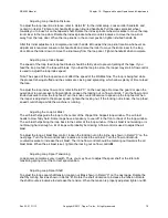
Page 69: ... previous page Raising and Lowering the Looper To raise or lower the looper referring to Detail B on the previous page loosen bolt A and the nut on bolt B The nut on bolt B is located on the back side of the looper assembly Loosen the lock nut on the jack bolt C Turn jack bolt C clockwise to raise the looper or counterclockwise to lower the looper When the looper is in the correct position tighten...

Page 70: ... Remove the guard or open the guard door to gain access to flow control L Loosen the locking nut on flow control L Turn the flow control knob clockwise to slow the loop feed Turn the knob counterclockwise to speed up the loop feed When the looper is adjusted to the proper speed tighten the locking nut If the locking nut is loose the loop feed speed could change while the machine is running Adjusti...

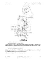
Page 71: ...e spring block to increase the tension on the loop idler arm Lower the spring block to reduce the tension Tighten bolt U when complete Adjusting Loop Strip Plates and Loop Brake Before a looper is shipped the Loop Strip Plates are adjusted using the following procedures After the Loop Strip Plates are adjusted they should not have to be adjusted in the field unless a clevis on any of the cylinders...

Page 72: ...er as shown in Detail C Tolerance buildup may require the use of some 99 1182 washers as shims between the jam nut and the clevis to get to the required positions Tighten the clevis jam nut when the adjustments are complete Lower Loop Strip Plate Adjustment The Lower Loop Strip Plate is positioned as shown in Detail E In the down position it is 562 from the Tape Backup Plate and in the up position...

Page 73: ...om under the clip or damage the loop If the gap is too big the loop may not have enough tension on the loop Without enough tension the loop end may come out from under the clip or the loop knot may end well away from the clip Set the gap on the loop door as shown in Detail F below Loosen the jam nut on set screw S Screw the set screw in to increase the gap Screw the set screw out to decrease the g...

Page 74: ......

Page 75: ...r air motor will provide years of trouble free service however the drive chain sprockets should be properly aligned to achieve maximum life from the motor and chain Misalignment will result in poor performance which will shorten the motor s life Always check the alignment after servicing and general maintenance 11 3 Air Motor Speed Controls The machine provides adjustable speed controls for the co...

Page 76: ... add oil to the lubricator ensure that the air supply is shut off and locked out and remove the filler plug Fill with oil to the level mark and replace the plug Turn on the air supply to the machine and turn the needle valve on top of the lubricator until the desired flow is achieved Monitor the rate of oil flow into the system using the sight glass on the top of the lubricator The preferred flow ...

Page 77: ...ious damage and system failure During emergencies the PLC output circuits must be turned off using either the EMERGENCY STOP pushbutton on the control panel or the main power switch located on the electrical control cabinet The PLC will continue to operate during momentary power failures less then 10 milliseconds If a power failure exceeds 10 milliseconds or if there is an abnormal voltage drop th...

Page 78: ...the power supply 2 Remove the terminal cover and open the panel cover 3 Remove the old battery from the holder 4 Ensure the polarity is correct and insert the connector onto the new battery The battery must be reconnected within 20 seconds after removal of old battery to prevent loss of programming 5 Replace the cover Caution Failure to connect the new battery within 20 seconds of removal of the o...

Page 79: ...formation about the PLC and battery functions The following examples show the PLC error help screen followed by low battery voltage error screen The programmable controller should provide years of trouble free performance if these operating instructions and precautions are followed If however the system fails or if it must be reprogrammed contact Tipper Tie immediately ...

Page 80: ......

Page 81: ...ver the operator interface assembly with a plastic bag Caution The use of excessively caustic sanitizer solutions will adversely affect the finish of many of the components on the machine 13 2 Disassembly for Cleaning Disassemble the machine for cleaning as follows 1 Press stop on the system control console stopping all machine functions and prepare to perform all lockout procedures 2 Open and clo...

Page 82: ...and sanitize all surfaces according to current safety rules 9 While cleaning inspect for worn or damaged components that may need to be replaced 10 After cleaning rinse the machine with a low pressure wash then blow off the machine with air 11 After cleaning rinsing and air blowing spray a light coating to all surfaces of the entire machine using a 10 weight food grade mineral oil 12 Coat the void...

Page 83: ...nife block assembly shown disassembled for daily cleaning Warning Very sharp knife edge M5 x 16 mm long hex head bolt Knife block 35 degree angle Knife 3 32 x 3 4 long spring pin press fit M6 x 50 mm long shoulder screw Male air connector Knife cover 35 degree angle Knife assembly M10 hex nut Knife assembly Knife cylinder bracket Washer plate 6 mm flat washer 6 mm x 20 mm shoulder screw ...

Page 84: ...ng Procedures Rev 32 01 11 13 Copyright 2013 Tipper Tie Inc All rights reserved 84 Disassembling the Pivot Rotor Assembly The pivot rotor assembly should be cleaned daily Disassembly of the unit is shown in the following illustration ...

Page 85: ...e maintenance trends Warning Push the Emergency Stop E Stop button to terminate all machine functions Warning Prior to performing any service or maintenance disconnect and lock out the electrical and air supplies After performing any service or maintenance before you return the machine to operation always check for and tighten any loose screws bolts and nuts connectors and hoses Inspect all of the...

Page 86: ...describes procedures for controlling moisture and corrosion Moisture Control To control moisture that can accumulate in the electrical and pneumatic control boxes in the operator interface touchscreen box and in the remote pushbutton box desiccant bags are included in each of the boxes The usable life of the desiccant bags can vary depending on operating conditions in the facility The desiccant ba...

Page 87: ...synthetic oils thinner solvents trichloroethylene kerosene and other aromatic hydrocarbons Therefore a metal bowl is required 14 5 Air Lubricators The RS4203CM uses three lubricator units the main lubricator the conveyor air motor lubricator and the voider rotary actuator lubricator Each of the machine s three lubricator units should be checked daily and refilled as needed The main lubricator is m...

Page 88: ...ked periodically for tightness The bearings that support the conveyor drive roller and the rollers in the conveyor roller carriage should be greased every day The conveyor air motor is maintenance free and does not have to be lubricated or disassembled for periodic maintenance However periodically check the tightness of the mounting bolts and drive shaft connections Check the air mufflers for accu...

Page 89: ...Manual Chapter 14 Maintenance Guide Rev 32 01 11 13 Copyright 2013 Tipper Tie Inc All rights reserved 89 Daily Clipper Pivot Clevis Daily Clipper Swing Eccentric Daily Voider Main Shaft Right End Bearing Block ...

Page 90: ...der Hub On right Daily Voider Main Shaft Stationary Voider Hub On left Weekly Voider Rotary Shaft Bearing Caution Do not over grease this fitting On right Daily Voider Eccentric On top left Daily Voider Main Shaft Left End Bearing Block Center Daily Voider Eccentric On bottom right Weekly Voider Rotary Shaft Bearing Caution Do not over grease this fitting ...

Page 91: ...n each block On left Weekly Conveyor Idler Roller 2 fittings 1 in front and 1 on back of roller Caution Do not over grease this fitting On right Daily Conveyor Shuttle Roller 1 fitting only Weekly Conveyor Drive Roller Bearing 2 fittings one on each side of roller Note The opposite side fitting is under the guard Caution Do not over grease these fittings ...

Page 92: ...a daily weekly quarterly semi annual and annual basis To help you track scheduled maintenance activities a sample of a machine maintenance log has been included in Appendix 2 Make copies of the sample or use your own form to record all service and maintenance activities and to track your PM program To obtain replacement items use the part numbers listed in the spare parts list in Chapter 17 or on ...

Page 93: ...erred drip rates are shown ___ Main lubricator unit one drop of oil for every 10 15 machine cycles ___ Conveyor air motor lubricator one drop for every 15 20 cycles ___ Voider rotary actuator lubricator one drop for every 10 cycles 14 8 2 Grease lubrication fittings Apply grease to the following lubrication fittings each day prior to running the machine Refer to Section 14 7 Mechanical Systems Lub...

Page 94: ...order to improve their adjustability 14 8 5 Inspect conveyor ___ Inspect belt condition ___ Check to ensure that all fasteners are tight ___ Move the conveyor chain or belt drive and the idler rollers to ensure they roll smoothly and freely 14 8 6 Inspect voider assembly ___ Inspect the voider and skin brake assembly for any loose parts ___ Inspect conveyor belt and bearings for excessive wear and...

Page 95: ...eparate away from fixed voiders ___ Clipper swings down in between both pairs of voiders ___ Clipper gate closes ___ Clipper punch extends down and knife is fired ___ Clipper gate opens clipper swings back and both voiders open ___ Movable voiders retract towards fixed voiders ___ Test Mode cycle has been completed ___ Check that all air gauges are functional clipper regulator and main incoming ai...

Page 96: ... week prior to running the machine Do not over grease these fittings Excessive grease in these closed units will clog the bearings and cause the assemblies to run intermittently or to stop completely Refer to Section 14 7 Mechanical Systems Lubrication earlier in this chapter for additional information and locations ___ Voider rotary shaft bearings 2 fittings ___ Conveyor drive roller bearings 2 f...

Page 97: ...ce resistance while moving past the gate and into the clipper s die ___ Inspect the clipper drive yoke and crank assembly for loose parts Check yoke for excessive play due to worn bushing yoke or key Tighten the set screw holding the yoke s retaining key Replace if necessary ___ Check and clean dies punches and clip channel rails of wax and aluminum buildup ___ Check that crimp stop knob is in pla...

Page 98: ...__ Skin brake housing floats on end of horn ___ Horn protrudes at least 125 inch 3 17 mm through skin brake housing ___ Movable voiders retract towards and flush with fixed voiders ___ Both pairs of voiders close ___ Movable voiders extend or separate away from fixed voiders ___ Clipper swings down in between both pairs of voiders ___ Clipper gate closes ___ Clipper punch extends down and knife is...

Page 99: ... the F R assembly ___ Main F R filter cleaned or replaced ___ Bowl base cleaned 14 10 2 Clean or replace filter elements ___ Check clean or replace filter elements ___ Common exhaust elements are cleaned or replaced 14 10 3 Inspect proximity switches and cables Inspect each cable for any signs of damage and replace as required ___ Cables inspected for signs of damage and replaced if necessary 14 1...

Page 100: ... complete cycle Note During this step ensure the horn engages the skin brake properly and that the housing floats on the horn ___ Observe for proper tracking of conveyor belt and adjust length of tension belt bolts if needed ___ Skin brake housing floats on end of horn ___ Horn protrudes at least 125 inch 3 17 mm through skin brake housing ___ Movable voiders retract towards and flush with fixed v...

Page 101: ...e two desiccant bags in the control box ___ Replace the desiccant bag in the operator interface box ___ Replace the desiccant bag in the remote control box 14 11 4 Inspect for Safety Re activate the machine by applying both air and electrical power to the machine ___ Inspect and close each guard and ensure proper powering up of machine by checking and resetting the EMERGENCY STOP button 14 11 5 Ru...

Page 102: ...r gate opens clipper swings back and both voiders open ___ Movable voiders retract towards fixed voiders ___ Test Mode cycle has been completed ___ Check that all air gauges are functional clipper regulator and main incoming air 14 11 6 Notify Production Notify production that maintenance and setup is complete and the machine is ready for operation 14 11 7 Observe Proper Lubrication Before signing...

Page 103: ...control box side wall 14 12 3 Re spray boxes with cleaner protectant ___ Re spray with cleaner protectant in both the Control Box and the Operator Interface Control Panel box using a single spraying with a Z shaped spraying pattern Note This step is not necessary if the desiccant bags and corrosion inhibitors have been replaced as scheduled 14 12 4 Inspect for Safety Re activate the machine by app...

Page 104: ...own and knife is fired ___ Clipper gate opens clipper swings back and both voiders open ___ Movable voiders retract towards fixed voiders ___ Test Mode cycle has been completed ___ Check that all air gauges are functional clipper regulator and main incoming air 14 12 6 Notify Production Notify production that the maintenance and setup procedure is complete and that the machine is ready for operati...

Page 105: ...he clipper is low Check the pressure setting and increase if necessary 4 Air lines are pinched Replace the air lines 5 Cylinder is stuck First check for pinched air line and check the air pressure If cylinder is still stuck disconnect air line and check for broken or worn parts Replace bad parts or air cylinder Punch does not retract 1 Punch extend valve may fail to reset Remove and clean valve sp...

Page 106: ......

Page 107: ... diameters use a sizing ring whenever applicable This adds to the uniform tension applied to the casing as it enters the skin brake It also prevents excessive overlapping of casing in the skin brake which can cause the product to stuff at an angle through the voider plates Check for damage to shoulder of chub such as nicks cuts and stress marks PROBLEMS SOLUTIONS Nicks very close to the clip Check...

Page 108: ...clipper drive tie rod to increase travel of clipper Casing rope should rest tightly down in against back of clipper throat Too much residual or product emulsion inside casing rope causing casing to rupture at clips when clips are applied just before knife is fired If turning voider adjustment wheel clockwise as described above does not sufficiently eliminate product from rope adjust orifice of mov...

Page 109: ...p attain the recommended stuffed diameter Over compensating with the skin brake adjustments can in some cases cause irregular product shapes and clip blow offs Product diameter oversized Check and decrease skin brake tightness confirm proper functioning of skin brakes Check conveyor height and speed Check orifice ratio between voiders Look for any signs of additional pressure being placed on horn ...

Page 110: ...ring due to worn adjustment blocks on movable voiders resulting in movable orifice being larger than stationary Clip slippage or blow off due to a malformed clip Ensure adequate lubrication is occurring Inspect die and punch ends for chipping or other defects and replace Inspect clip feeding system to ensure clips are not being damaged prior to entering clip channel Inspect clips for inadequate lu...

Page 111: ...e spare parts and installation kits are included in the following assembly drawings 00 3021 RS4203 RS4203AB Installation Kit 00 2888 RS4203 Spare Parts Kit 00 4270 Z4270 Spare Parts Kit 17 2 Pneumatic Part number Description Quantity 24 0006 Punch regulator 1 24 0097 Water separator element 1 40 0044 O ring 1 17 3 Conveyors 25 0051 Air motor 1 30 0282 Trip roller proximity switch 1 57 0569 Timing ...

Page 112: ...of casing material compressed in length to match the usable horn length The usable horn length for the casing by horn diameter is Horn Diameter Allowable casing slug length 1 1 16 diameter 27 mm 25 inches 635 mm 1 9 16 diameter 39 7 mm 25 5 inches 647 7 mm 2 1 16 diameter 52 4 mm 27 inches 685 8 mm 2 9 16 diameter 65 1 mm 28 inches 711 2 mm 3 1 16 diameter 77 8 mm 28 inches 711 2 mm 17 6 Gasket an...

Page 113: ...3 Assembly Z4270M Clipper with Stick Clips Z4270RP Clipper with Reel Pan 00 1568 Knife Cylinder 00 1569 Gate Cylinder 00 1570 Punch Piston 00 1580 Lower Clip Pusher LH 00 1581 Lower Clip Pusher RH 00 1582 Upper Clip Pusher LH 00 1583 Upper Clip Pusher RH 00 1706 Lower Reel Pan 00 1707 Upper Reel Pan 00 1708 Reel Pan Brake Cylinder 00 1736 Clipper Mount 00 1737 Clipper Rotary Actuator 00 1752 Clipp...

Page 114: ...tion 00 2885 3 Horn Rotor 00 2886 4 Horn Rotor 04 0446 Cylinder Mount for 00 1756 Skin Brake Slide 50 0400 3 Inner Vacuum Ring Horn 50 0404 4 Inner Vacuum Ring Horn 50 0550 Double skin brake Horn kit used on 00 1758 Skin Brake Slide 3 Position 50 0800 Double skin brake Horn Kit used on 00 1756 Skin Brake Slide 2 Position 18 6 Voiders 00 1523 Slack Fill 00 1524 Non Slack Fill 00 1525 Frame 00 1551 ...

Page 115: ...r 00 3072 72 Conveyor T10 Single Belt Conveyors Used on machines after October 2004 00 2206 Conveyor Nose Roller Assembly 00 2207 Conveyor Roller Carriage Assembly 00 2208 Conveyor Hitch Bar Assembly 00 2278 Conveyor Drive Roller Assembly 00 2279 Conveyor Air Motor Assembly 57 3048 48 Conveyor assembly 57 3060 60 Conveyor assembly Note Product diverter is an option 57 3072 72 Conveyor assembly Not...

Page 116: ...s above 00 2187 Dump Conveyor Trip Paddle Assembly 00 2188 Dump Sensor Mount Assembly 00 2189 Conveyor Dump Paddles Assembly 00 2191 Dump Conveyor End Tray Assembly 00 2199 Dump Conveyor Reverse Trip Paddle 73 0045 Dump Conveyor Control Box Assembly 73 0046 Dump Conveyor Control Panel Assembly 18 9 Schematics 63 4215 Electrical Schematic 63 4216 Pneumatic Schematic Two schematics with the same con...

Page 117: ...ly Drawings Rev 32 01 11 13 Copyright 2013 Tipper Tie Inc All rights reserved 117 Water Separator Retrofit Kits 00 2746 RS4203 Water Mist Separator Kit for Air Prep 00 2877 RS4203 Adding Water Separator to the Conveyor Air Motor Kit ...

Page 118: ......

Page 119: ...y Range Continuous Sound Levels recorded at 76 6 dB The standard indicates that the eight 8 hours exposure level shall not exceed 85dB without hearing protection Peak instantaneous sound pressure value C Weighted scale 1000 Hertz Frequency Range Peak instantaneous Sound Pressure Values recorded at 97 7 dB The standard indicates that the Peak Instantaneous Sound Pressure Level Shall not exceed 130d...

Page 120: ......

Page 121: ...c All rights reserved 121 Appendix 2 Maintenance Log Make copies of this maintenance log or use your own form and use the log to record all preventive maintenance and unscheduled service activities Use the log to identify and isolate adverse trends Date Technician Maintenance Performed ...

Reviews: