background image

2

safety notes 

FAILURE TO HEED THE FOLLOWING WARNINGS MAY 

RESULT IN SERIOUS INJURY OR DEATH! 

Operators must be trained in the proper, safe operation of the hoist.

Hoists are 

not

 to be used to lift, raise, or move people.  If your task involves lifting or moving

people, you 

must

 use the proper equipment, not this hoist.

Cable anchors on hoists are not designed to hold the rated load of the hoist.  You must keep at

least five (5) wraps of cable on the drum to ensure that the cable doesn't come loose.

Stay clear of suspended loads and of cable under tension.  A broken cable or dropped load can

cause serious injury or death.

Avoid shock loads.  This type of load imposes a strain on the hoist many times the actual weight

of the load and can cause failure of the cable or the hoist.

Make sure that all equipment, including the hoist and cable, are maintained properly.

Summary of Contents for TWG TULSA WINCH 707W

Page 1: ...AND THEORY OF OPERATION 3 HYDRAULIC SCHEMATIC 4 MAINTENANCE AND SERVICE 5 WIRE ROPE 7 DISASSEMBLY 8 ASSEMBLY 9 SERVICING THE MOTOR 10 SERVICING THE BRAKE 11 SERVICING THE PLANETARY SET 13 TROUBLESHOO...

Page 2: ...on hoists are not designed to hold the rated load of the hoist You must keep at least five 5 wraps of cable on the drum to ensure that the cable doesn t come loose Stay clear of suspended loads and o...

Page 3: ...ake When the load comes to a stop the cam clutch locks up and the brake prevents the load from moving During payout a brake valve is used to prevent the load from moving faster than desired This brake...

Page 4: ...4 HYDRAULIC SCHEMATIC...

Page 5: ...month API RP 2D recommends a pre use inspection and an annual 12 month inspection based on average use over a quarter For hoists in moderate use more than 10 but less than 50 hours per month API RP 2D...

Page 6: ...fall resulting in property damage personal injury or death The hydraulic system should use only high quality hydraulic fluid from reputable suppliers These oils should contain additives to prevent fo...

Page 7: ...33 located in the center of the shaft Fill the gearbox with 1 00 quart of EP 90 oil Remove the pipe and elbow then replace the plugs Item 33 See the Oil Chart on page 6 of this manual for the recommen...

Page 8: ...m Item 5 Inspect the bearing Item 28 for signs of pitting or spalling and if necessary replace the bearing and seal Item 7 3 7 Remove the sun gear Item 8 from the planet gearset Item 4 Inspect for dam...

Page 9: ...output shaft 10 Install a new o ring Item 7 6 and if necessary a new bearing Item 28 and seal Item 7 3 into the bearing carrier Item 26 Grease the o ring and seal and install the bearing carrier into...

Page 10: ...he motor assembly 2 Remove the counterbalance valve from the block Item 42 and inspect the small metering hole located on the side of the valve to make sure it is not obstructed Also inspect the o rin...

Page 11: ...the journal on the brake housing where the seal Item 7 3 runs for wear If severely worn replace the brake housing 8 Carefully disassemble the brake driver clutch and note the side in which the marking...

Page 12: ...nto the brake housing Item 21 and draw it down evenly alternating between opposite capscrews Item 9 Make sure that the cover is aligned properly with the brake housing in order to correctly orient the...

Page 13: ...bearings and gear bores for evidence of wear and replace if necessary 5 Before reassembly be sure to insert the thrust plate into the carrier 6 To reassemble be careful to line up the planet pins with...

Page 14: ...le Solutions 1 The relief valve setting may be too low to allow proper lifting Increase the relief pressure setting 2 The load being lifted may be more than the hoists rating Verify weight and reduce...

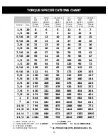
Page 15: ...7 45 106 80 64 1 2 20 85 64 51 120 90 72 9 16 12 109 82 65 153 115 92 9 16 18 122 91 73 172 129 103 5 8 11 150 113 90 212 159 127 5 8 18 170 128 102 240 180 144 3 4 10 266 200 160 376 282 226 3 4 16 2...

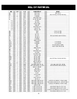
Page 16: ...2765 FRICTION DISC 19 6 42148 STATOR PLATE 20a 1 42172 BRAKE COVER 20b 1 42401 BRAKE COVER 20c 1 42552 BRAKE COVER SEE PICTORAL FOR DESCRIPTION 21 1 42171 BRAKE HOUSING 24 12 41718 BRAKE SPRING 25a 1...

Page 17: ...OUTPUT SIDE SEE PICTORAL FOR DESCRIPTION 51a 2 43857 CAPSCREW 52 2 43856 LOCKWASHER 55a 3 43858 CAPSCREW 55b 8 31558 CAPSCREW 55c 4 43111 CAPSCREW MATCH QTY WITH PROPER MOUNT 57 1 12208 BUSHING 60 4 4...

Page 18: ...18 EXPLODED ISOMETRIC ASSEMBLY DRAWING TWG PO Box 1130 Jenks OK 74037 1130 USA Phone 918 298 8300 www dovertwg com...

Reviews: