background image

4 OM-ECOARCH

Fresh Air Supply Fan

1.   Check all local codes prior to installation.
2.   Supply fan inlet must be located to minimum 10’-0” from the exhaust fan. If 

10’ is not possible a 3’ vertical separation may* be acceptable.

3.   Cut and seal supply fan curb to roof.
4.   Duct shall be constructed of 22 or 24 gauge steel. Insulated duct material 

should be used to eliminate frost and/or condensation.

5.   Duct shall be sized to provide air velocities not exceeding 1200 FPM.
6.   A volume control damper, provided in the duct just above the supply collar 

that contains the UL listed  re damper, should be properly set to supply CFM 
required.

7.   If the hood is provided without the supply collar installed, it must be installed 

per the instructions provided on the collar.

8.   Carefully place the supply fan on roof curb. Face supply fan inlet away from 

prevailing winter wind. Electrical back draft damper is recommended in cold 
climates.

9.   Bolt or screw fan to fan curb.
10. Make all necessary electrical connections and check fan for proper rotation.
NOTE: Fan will supply air running in wrong direction. *Dependent on local code 
requirements.

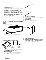
SIDE SKIRTS

One or two side skirts may be provided.

1.   Side skirts are offset at the top and have a 90° bend inward at the rear.
2.   Skirts are to overlap the outside of the hood. Bolts and acorn nuts should be 

attached per the drawing (stainless bolts and acorn nuts supplied).

3.   Skirt flange should be screwed to the wall (screws not provided).

TOP ENCLOSURES

Enclosure panels are provided for exposed side(s) of hood(s).

1.   Hoods ordered with enclosure panels will be shipped with clips installed on 

perimeter of hood top where panels are to be installed. 

2.   Slide enclosure panel under clips. 
3.   If enclosure panels are installed on one or more hoods butted end to end, the 

butting ends of the front enclosure panels should be bolted together.

INSULATED WALL PANEL

Insulated wall panel comes in multiple pieces.

1.   Install wall panels prior to hanging hood(s).
2.    Install first panel at one end.  Top of panel should be installed 6’-6” A.F.F. and 

level. Screw panel to wall.

3.   Install any additional panels
4.   Caulk vertical seam with NSF approved silicone sealant.
5.   When hood is hung it will rest on top panel.
NOTE: Be careful to not damage wall panel face when installing hood.

SINGLE THICKNESS WALL PANEL

1.   Install wall panels prior to hanging hood(s).
2.   Install seam strips at proper locations and screw to wall.
3.   Apply glue to wall between seam strips.
4.   Slip one end of wall panel into seam strip, pull out middle of panel and slip 

other end of panel into other seam strip. Gently apply pressure over entire 
wall panel to secure to wall. Wall bands for side walls are provide with 1” 
return bend, which is to be located behind rear wall panels. 

Summary of Contents for Unified Brands Avtec EcoArch

Page 1: ...r extinguishing systems may be factory supplied ULTRAVIOLET UV SERIES The EcoArch Energy Efficient Ventilation UVc is a door assembly integrally installed in the exhaust plenum of an EcoArch canopy consisting of UVc filtration system designed for use in the ventilation control of commercial cooking operations of listed hood systems A depiction of this unit is indicated at left The UVc filtration s...

Page 2: ... VOLUME CONTROL DAMPER FLUID WELD Installation Instructions LT D D Avtec hoods are provided with adjustable hanging brackets designed to receive 1 2 threaded rod with a 1 2 nut and washer Supporting rods must be connected to all factory installed brackets Recommended hanging height is 6 6 above finished floor for canopies Low side wall ventilators should be installed directly upon a Avtec base or ...

Page 3: ...The exhaust fan curb should be installed directly above the hood if possible Always maintain the shortest duct run possible 4 Cut hole and seal exhaust fan curb to roof 5 Duct shall be sized to provide air velocities not exceeding 1200 FPM 6 Install hinges and airline cable on exhaust fan cap and metal curb Remember to leave ample room for fan to tilt back Fan will remain in tilted back position 7...

Page 4: ...he outside of the hood Bolts and acorn nuts should be attached per the drawing stainless bolts and acorn nuts supplied 3 Skirt flange should be screwed to the wall screws not provided TOP ENCLOSURES Enclosure panels are provided for exposed side s of hood s 1 Hoods ordered with enclosure panels will be shipped with clips installed on perimeter of hood top where panels are to be installed 2 Slide e...

Page 5: ...ot run the exhaust fan 2 Refer to drawings or UL information label on hood for proper CFM requirements PERIODIC MAINTENANCE WARNING ELECTRICAL SHOCK HAZARD DISCONNECT POWER BEFORE SERVICING REPLACE ALL PARTS AND PANELS BEFORE OPERATING FAILURE TO DO SO CAN RESULT IN DEATH OR ELECTRICAL SHOCK CAUTION MAKE SURE ALL COOKING EQUIPMENT THE EXHAUST HOOD AND UVC EXHAUST AIR CLEANER HAVE BEEN TURNED OFF A...

Page 6: ... there has been a breach of warranty by UNIFIED BRANDS must give us written notice within THIRTY 30 days after discovery of the relevant defect or the right to assert such claim will have been waived conclusively and provided further that any such claim must also be asserted within the general warranty period for such equipment and or parts UNIFIED BRANDS will not be liable for any expense incurre...

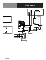
Page 7: ...7 OM ECOARCH Wiring Diagram RELAY BOX BALLAST BOX ...

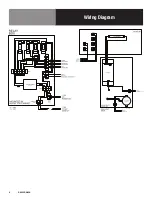
Page 8: ...8 OM ECOARCH Wiring Diagram ...

Page 9: ...9 OM ECOARCH Service Log Model No Purchased From Serial No Location Date Purchased Date Installed Purchase Order No For Service Call Date Maintenance Performed Performed By ...

Reviews: