5 OM-ECOARCH
START/CHECK/BALANCE
DIRECT DRAW HOODS
1. Close all doors and windows.
2. Operate all exhaust fans, even fans serving other hoods, make-up air units
and building HVAC.
3. Turn on all cooking equipment under the hood to preheat to operating
temperature.
4. Produce large quantities of smoke.
5. Observe capture of vapors.
6. If all vapors are not captured, increase exhaust fan RPM.
7. Check air pressure in kitchen. Pressure must be negative relative to dining
room pressure.
8. Air velocities entering the kitchen from the dining room should not exceed
100 FPM.
No air should be moving toward the dining area.
9. Repeat steps 6 and 7 until all vapors are captured.
10. Same as step 7 with bottom of next section.
NOTE: The exhaust and supply (if any) air flow rates were established under
controlled laboratory conditions, and greater exhaust and/or lesser supply air
may be required for complete vapor and smoke removal in specific installations.
MAKE-UP AIR HOODS EXHAUST FAN(S)
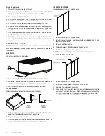
1. Open all doors and/or windows leading to outside.
2. Start the exhaust fan only. Do not run the supply fan or make-up unit.
3. Refer to drawings and/or UL information label on hood for proper CFM
requirements.
4. Adjust speed of exhaust fan to obtain proper air velocities and CFM through
grease filters.
Final Balance
1. Close all doors and windows.
2. Operate all exhaust fans even those serving other hoods, supply fans, make-
up air unit and building HVAC system.
3. Turn on all cooking equipment under the hood and preheat to operating
temperature.
4. Produce large quantities of smoke or steam.
5. Observe capture of vapors.
6. If all vapors are not totally captured, fine tune the system by adjusting the
air volume control damper installed in the supply collar. Slightly reduce the
amount of supply air directed under the hood until full capture is obtained.
SUPPLY FAN OR MAKE-UP AIR UNIT
1. Start the supply fan and/or make-up unit only. Do not run the exhaust fan.
2. Refer to drawings or UL information label on hood for proper CFM
requirements.
PERIODIC MAINTENANCE
WARNING: ELECTRICAL SHOCK HAZARD! DISCONNECT POWER BEFORE SERVICING.
REPLACE ALL PARTS AND PANELS BEFORE OPERATING. FAILURE TO DO
SO CAN RESULT IN DEATH OR ELECTRICAL SHOCK.
CAUTION: MAKE SURE ALL COOKING EQUIPMENT, THE EXHAUST HOOD AND UVC
EXHAUST AIR CLEANER HAVE BEEN TURNED OFF AND ALLOWED TO COOL.
HOT EQUIPMENT CAN CAUSE BURNS.
CAUTION: USE STEP LADDER OR OTHER STABLE PLATFORM TO PROVIDE EASY
ACCESS TO THE INTERIOR OR THE UVC LAMP CABINET. DO NOT STAND ON
COOKING EQUIPMENT TO SERVICE THE UVC. FALLS CAN CAUSE SERIOUS
INJURIES.
BAFFLE FILTERS
Filters should be removed and cleaned at least weekly, depending on hours of
operation. Filters may be cleaned by soaking in a strong detergent solution or
running thru a dishwasher. When replacing, make sure filters and handles are
running vertically, and filters are seated properly.
MODULAR GREASE EXTRACTORS
Modules should be removed and cleaned at least weekly, depending on hours of
operation. Modules may be cleaned with a brush and a strong detergent solution
or run thru the dishwasher. When replacing modules, make sure they are seated
properly.
GREASE TROUGH
Should be checked weekly for grease build up and cleaned with strong detergent
if necessary.
GREASE COLLECTION RECEPTACLE
Should be emptied at least once a day and cleaned daily with a strong detergent.
HOOD CANOPY
Inside hood canopy should be wiped down as needed. The area at the exhaust
intake openings should be wiped down daily.
Inspect inside of extraction chamber at least weekly to insure proper cleaning
and that the trough and access door are free of foreign matter.
UV PREVENTATIVE MAINTENANCE
Clean the UV lamp at the same time the grease extractors are being cleaned (or
daily), wipe down the UV lamp exterior using a dry towel and a non-detergent
cleaning agent such as sanitizing solution or white vinegar.
IMPORTANT: Do not allow cleaner to run into lamp fittings or socket enclosures.
IMPORTANT: UV System will not work properly without daily cleaning of the UV
lamp.


