5
OM-DH(T) DOMESTIC & (CE) INTERNATIONAL
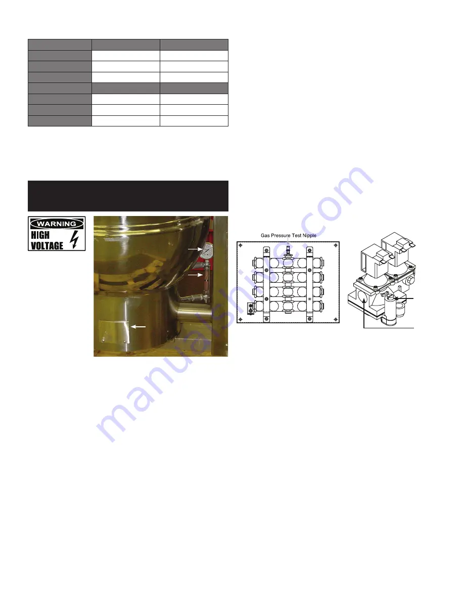
A pressure test point is fitted on the burner manifold and on the gas control valve.
Natural (G20) Models
mBar
WCI (Water Column Inches)
DH-20
8.75
3.5
DH/1-40
8.75
3.5
DH-60
8.75
3.5
Propane (G31) Models
mBar
WCI (Water Column Inches)
DH-20
25
10.0
DH/1-40
25
10.0
DH-60
25
10.0
BURNER ADJUSTMENT
The burners are fixed aeration type and have no provision for adjustment of air inlet.
INITIAL START-UP
CAUTION: ENSURE THAT THE KETTLE CONTAINS LIQUID WHEN THE BURNERS ARE
ALIGHT.
WARNING: THIS APPLIANCE MUST BE EARTHED.
Water Level
Gauge &
Sight Glass
Pressure
Gauge
Gas Valve
Access Cover
GAS SUPPLY
Connect the unit to the gas supply and test for gas soundness. For gas supply
down stream of the gas valve, leak detection spray or soap solution may be used
with the burners lit.
ELECTRICAL SUPPLY
Before commissioning the appliance, ensure that the electrical installation has
been carried out to the relevant regulations (see Installation section).
JACKET WATER LEVEL/JACKET PRESSURE
Ensure the water level in the jacket is correct, by confirming that it is between
the sight glass marks. If it is low, follow instructions in Servicing and Conversion
section, Jacket Filling.
Check the pressure gauge. If it does not show 20 or more inches of vacuum (that
is, a reading of 20 to 30 below zero) see Servicing and Conversion section, Jacket
Vacuum.
PRE-COMMISSIONING CHECK
1. Prior to operation, clean out kettle thoroughly using hot water and detergent.
Rinse kettle thoroughly.
2. Remove all literature and packing materials from the interior and exterior of
the unit.
3. Ensure the open end or the elbow at the outlet of the safety valve is directed
down. If not, turn the elbow to the correct position. See detailed Instructions in
Servicing and Conversion section for Safety Valve installation and operation.
START-UP
Now that your kettle has been installed, you should test it to ensure that the unit
is operating correctly.
1. Remove literature and packing materials from the interior and exterior of the unit.
2. Put a small amount of water into the kettle (6 to 13 mm). With the kettle in the
horizontal position, note how the water lies in the kettle, to confirm that the
pan was leveled properly during installation.
3. Following the “To Start Pan” instructions for your kettle model, begin heating
the water at a temperature setting of 235ºF (113ºC). At this setting, heating
should continue until the water boils.
4. To shut down the unit, switch the power switch to OFF.
5. Turn the tilting handwheel counterclockwise to pour out the water and to
confirm that the kettle body can be tilted smoothly from horizontal to vertical.
If the unit functions as described above, it is ready for use. If it does not, contact
your local Authorized Service Agency (Domestic) or Engineer (CE).
After installing and commissioning the appliance, the user’s instructions should be
handed to the user or purchaser. Ensure that the instructions for lighting, turning
off, correct use and cleaning are properly understood. The location of the main gas
isolating valve should be emphasized and the emergency shut down procedure
should be demonstrated.
SETTING THE GAS PRESSURE
Capscrew
for Governor
Pressure
Adjustment
Gas Inlet
1. It is necessary to check the gas pressure during commissioning. A pressure
gauge must be connected to the pressure test point on the gas manifold. See
above figure for test points.
2. Turn the main gas and electricity supply on.
3. Light the burners.
4. Remove cover plate on the round skirt at bottom of kettle.
5. Remove governor cap screw from control valve. See above figure for position
on valve.
6. Governor adjustment is suitable for both natural and propane gas.
7. To increase pressure turn the screw inside the governor turret clockwise;
anti-clockwise to reduce pressure. Check the burner pressure again after 15
minutes operation and adjust if necessary.
8. Disconnect the pressure gauge from the test point. Re-seal the pressure test
point and test for gas soundness.
9. Replace governor cap screw and replace cover plate.
CHECKING PERFORMANCE OF CONTROLS
1. Light the unit. Check that controls quickly and smoothly produce a healthy
spark from the electrode to the earthing post.
2. Turn controller off and then on. Check that burners go out and reignite smoothly
and quickly when switched back on. Repeat several times.
3. If the unit fails to respond as described, it should be serviced by an authorized
Groen service agent.
Summary of Contents for unified brands groen DH-20
Page 16: ...16 OM DH T DOMESTIC CE INTERNATIONAL Parts List GAS VALVE PIPING BOTTOM COMPONENTS ...
Page 27: ...27 OM DH T DOMESTIC CE INTERNATIONAL Wiring Diagram Domestic For Classic Control Models ...
Page 28: ...28 OM DH T DOMESTIC CE INTERNATIONAL Wiring Diagram Domestic For Advanced Control Models ...
Page 29: ...29 OM DH T DOMESTIC CE INTERNATIONAL Wiring Diagram CE ...


