14
3. Installation of the Appliance
3.1 Decide whether to use top or rear flue exit.
The appliance is factory built for rear flue exit but it can be
changed to top exit by swapping the flue spigot and blanking
plate located on the appliance.
3.2 Position the appliance ensuring all appropriate clearances
are observed.
3.3 Having run the gas supply to the appliance PURGE THE
SUPPLY PIPE.
This is essential to expel any debris that can block the gas
controls.
3.4 Connect the gas supply to the 8mm-compression elbow at
the right-hand rear corner of the appliance
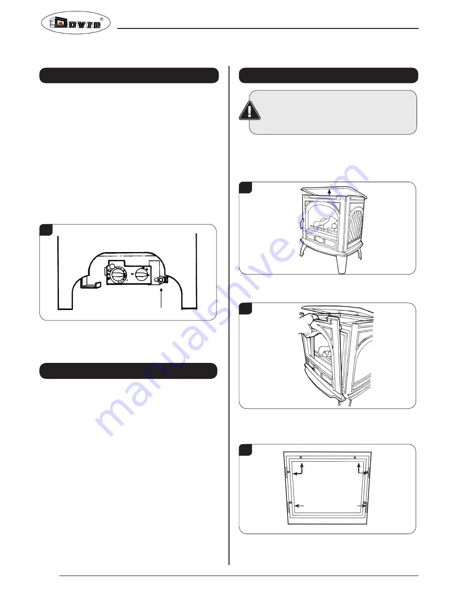
There is a cutout in the right-hand rear leg to enable a
straight connection to the rear of the appliance,
see Diagram 1.
1
3.5 The flue system can now be connected to the appliance.
3.6 Ensure all joints are sealed with a fire resistant cement and
use a self-tapping screw at the flue spigot joint.
4. Gas Soundness Pressure Check
4.1 Connect a suitable pressure gauge to the test point located
on the inlet fitting and turn the gas supply on. Light the
appliance and check all gas joints for possible leaks. Turn
the appliance to maximum and check that the supply
pressure is as stated on the databadge. Turn the gas off
and replace the test point screw, turn the gas on and check
the test point for leaks.
Installation Instructions
5. Removing the Door
IMPORTANT: THE OUTER PANELLING OF THE
APPLIANCE IS MADE FROM CAST IRON. USE
CAUTION WHEN INSTALLING, REMOVING AND
STORING AS THE COMPONENTS ARE HEAVY
AND SHOULD BE HANDLED CAREFULLY.
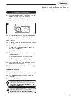
5.1 For rear flue exit lift the top of the appliance off and put to
one side.
5.2 For top flue exit lift and support the top to give clearance,
see Diagram 2.
2
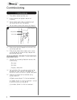
5.3 Lift the front upwards until it is clear of the slots and pull
away from the appliance, see Diagram 3.
3
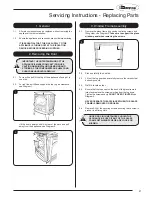
5.4 Remove the glass frame by undoing the fixing screws and
lifting clear, see Diagram 4. Take care to support the glass
window panel when removing the screws.
4
Summary of Contents for 280
Page 28: ...E O E ...


