S 100 FM BT
Technical characteristics
Nr. of channels...................................1 stereo channel
Amplifier..............................................1.5+1.5W stereo
Bluetooth............................................A2DP transmission protocol
Minimum load impedance................8 ohms
Power supply......................................12Vcc/330mA
Stand-by power consumption........25mA
Operational power consumption..69mA
Connectors.........................................Strip terminals
Dimensions.........................................44 x 44 x 36mm depth
CONTROL
MODULE WITH
BLUETOOTH
S 100 FM
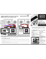
WIRING DIAGRAM FOR S 100 FM BT CONTROL
MODULE AND UC 100 S CENTRAL UNIT
NOTE.-
The
UC 100 S
supports a máximum of 10 sound control modules and a maximum distance of 100 mts.of cable to the last element to be controlled.
For higher installations, power supply units or a more powerful central unit would be required.
HOW TO PROGRAM THE SYSTEM:
Once all the system units are already installed, a zone number must be assigned to each control module as follows:
1st.- Keep the keys <> pressed during 4 seconds. The number “1” will be shown on the displays of ever y control module.
2nd.- Choose the control module you want to be the “zone 1” and press the On/Off key. The number “1” will be memorized as a zone number in
that control module.
3rd.- Now the rest of control modules will show the number “2” in their displays. Choose again which control module you want to be the “zone 2”
and press the On/Off key of that module.
4th- Repeat the process as many times as control modules/zones are in the installation.
5th- Once the zone assignment is finished, keep the control module on/off key pressed during 4 secondsin order to leave the “assingnment zone mode”.
System with power supply unit
0
5
-
+
+
-
R+ R- L- L+
0 5 8 9
C1L C1R
MAINS 230 Vca.
2x0,75 mm.
0
5
8
9
-
+
+
-
C1L
C1R
CABLE REF. W-8
MINIMUM SECTION
2X1 MM
6x0.25 MM
R+ R- L- L+
0 5 8 9
C1L C1R
S 100 FM BT
UC 100 S
System with central unit
For AUXILIARY CONNECTION of audio, TV, PC, etc. please
use 0 (ground) and C1L and C1R (Left and right channel 1)
M
M
M
VOLUME, SCAN FM...
AUXILIARY AUDIO INPUT
ON/OFF KEY
MICROPHONE
MENU CONTROL KEY
LCD DISPLAY
FM TURNER, AUDIO CHANNEL, AUX.
IN AND BLUETOOTH SELECTOR
ANT
0
5
8
9
M
C1 R
C1 L
GROUND - Vcc
POWER SUPPLY 12 +Vcc
COMMUNICATIONS
COMMUNICATIONS
MICROPHONE AUDIO
RIGHT CHANNEL 1
LEFT CHANNEL 1
=
=
=
=
=
=
=
www.doyson.com
STEREO
ZONE
CABLE REF. W-2
MINIMUM SECTION
2X0.50 MM
Speaker
Ref. SP 5
STEREO
ZONE
CABLE REF. W-2
MINIMUM SECTION
2X0.50 MM
Speaker
Ref. SP 5
FA 12 BI
Power supply
unit
S o u n d & H o m e
A u t o m a t i o n
MAINS
ANTENNA CONNECTION:
Conductor wire of 80 cm. In zones of
bad reception, connection to outdoor antenna it is highly recommended.


