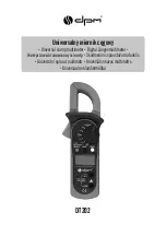
dt202
11
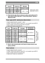
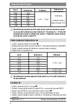
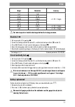
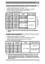
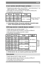
Range
Resolution
Accuracy
4 nF
1 pF
±4.0%+5 digits
40 nF
10 pF
400 nF
100 pF
4 µ
F
1 nF
40 µ
F
10 nF
400 µ
F
100 nF
±4.5%+5 digits
4 mF
1 µ
F
±5.0%+9 digits
The tested capacitor should be discharged before the testing procedure.
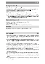
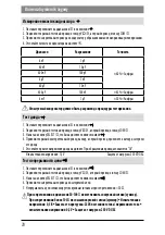
Diode test
1. Set range switch
O
to position .
2. Connect red testing cable to V
socket
R
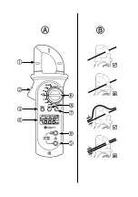
, and the black testing cable to COM socket (5).
3. Press SELECT button
L
until symbol will appear on the display
.
4. Attach the red gauging cable to anode and black cable to cathode of gauged diode.
5. Read diode’s conductiung voltage on the display (4). By the reversed cables “OL” will be displayed.
Test voltage: 1,5 V
Overload protection: 250 V DC/AC
Circuit continuity test
1. Set range switch
O
to position .
2. Connect red testing cable to V
socket
R
, and the black testing cable to COM socket
N
.
3. Press SELECT button
L
until symbol will appear on the display
.
4. Attach gauging cables to measured circuit.
5. Continuity of the circuit shall be flagged with an audio signal when resistance is lower than < 30
.
If the circuit resistance is in the range 30-100 an audio signal (buzzer) could appear.
In case of resistance > 100 an audio signal (buzzer) won’t appear Test voltage:
0,5 V Overload protection: 250 V DC/AC
Battery replacement
Battery should be replaced when LCD display shows an exhausted battery icon
.
1. Remove back cover of the multimeter.
2. Place new 2 x AAA batteries paying attention to proper polarization.
Disconnect all gauging cables from the multimeter and the gauged circuit prior to
removing the back cover.

