DPtech DPX19000 Series Deep Service Switching Gateway
Installation Manual
Chapter 1 Product introudction
10
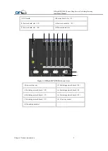
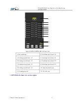
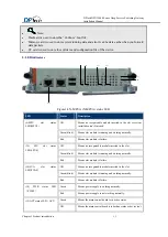
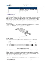
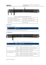
Figure1-7 Main control board (N-MPUA) front view
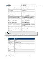
(1) Ethernet management port(MGMT)
(2) CONSOLE port(CON)
(3) USB port (0)
(4) USB port (1)
(5) MPU status LED(MPU1)
(6) MPU status LED(MPU2)
(7) LPU status LED(LPU1)
(8) LPU status LED(LPU2)
(9) LPU status LED(LPU3)
(10) LPU status LED(LPU4)
(11) Switching fabric module LED(Fabric1)
(12) Switching fabric module LED(Fabric2)
(13) Switching fabric module LED(Fabric3)
(14) Switching fabric module LED(Fabric4)
(15) Power status LED(PWR0)
(16) Power status LED(PWR1)
(17) Power status LED(PWR2)
(18) Power status LED(PWR3)
(19) MPU active-standby status LED(ACT)
(20) Switching fabric module fan tray status
LED
(
FAN0
)
(21) Switching fabric fan tray LED(FAN1)
(22) LPU fan tray status LED (FAN2)
(23) Ethernet management interface LED
(24) Reset button (RST)
(25) Wrench
(26) Captive screw
Note:
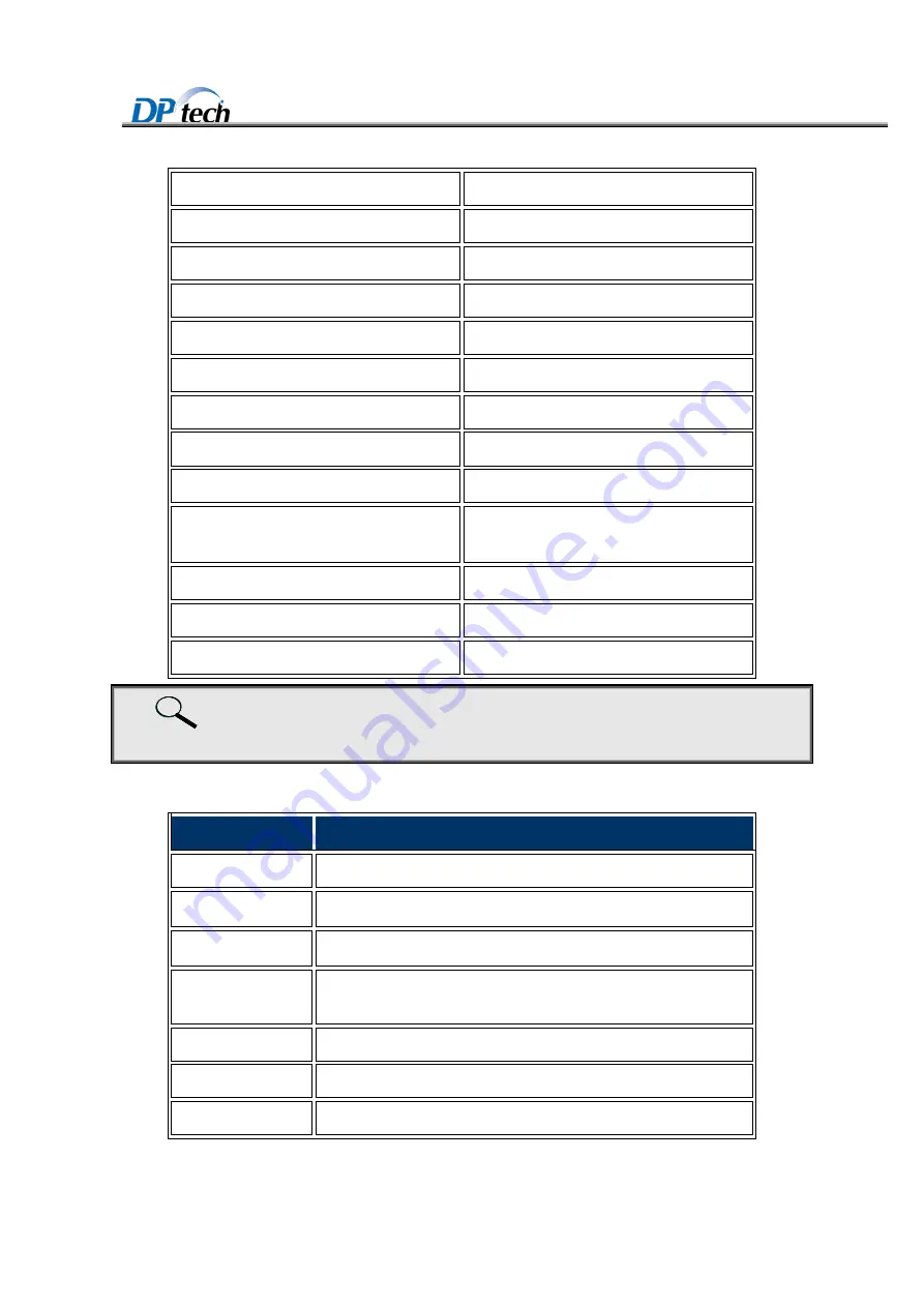
DPX19000-A18 supports dual MPUs. Their slot numbers are M1, M2.
2. Specification
Item
Specification
Flash
4MB
Memory size
DDR
Ⅱ
SDRAM 2GB
CONSOLE pot
1 console port (9600bps
~
115200bps), default is 9600bps
Ethernet management
port
1*10/100/1000BASE-T
CF card
2GB
USB port
2
Reset button
1
Summary of Contents for DPX19000 Series
Page 67: ...Chapter 6 Troubleshooting 1 ...


