background image


DPtech DPX19000 Series Deep Service Switching Gateway  
Installation Manual          


Chapter 3 Installation Preparation 


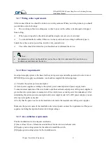
3.2.7  Wiring cable requirements 

Cables connect the device should be indoors, not wiring outdoors. When you wiring indoors, you should 

pay attention to the followings: 


Do not wiring cables in working area, so that it can avoid the cables to be damaged or dropped 

from ceiling. 


When you wiring cables, the cables should be straight, not curved, or not twined. 


You should bundle the cables if there are too many cables and according to different types to 

bundle the cables (such as power line, interface wire, ground wire)  


The cables should be labeled for your troubleshoot or dismount the device. 


  Note: 


Recommend you that you should label your cable, so that it is convenient for you when you 
troubleshoot and dismount the device. 


3.2.8  Power requirements 

Good power supply system is the basis for the system power-up and stable operation. In order to meet 

DPX19000 power supply requirements, you should accomplish the following steps: 


(1) Calculate the system power consumption. 

(2) Select power supplies according to the system power consumption and power supply mode. 

To ensure normal operation of the switch, make sure the maximum output power of the power supplies is 

greater than the system power consumption of the switch (reserve certain power for redundancy). After 

determining the system power consumption and power supply mode (AC or DC power supply), you can 

select power supplies as needed. 

(3)Verify that the power source on the installation site meets the requirements of the power supplies. 


Make sure the power source of the installation site is steady and can meet the requirements of the power 

supplies, including the input method and rated input voltage. 


3.2.9  Air-ventilation requirements 

Plan the installation site for adequate ventilation.


(1)

Leave at least 10 cm of clearance around the air intake vents and exhaust vents.


(2)

 Equip a good cooling system for the cabinet to install the switch.


(3)


Equip a good cooling system for the installation site.


Summary of Contents for DPX19000 Series

Page 1: ...DPtech DPX19000 Series Deep Service Switching Gateway Installation Manual i DPtech DPX19000 Series Deep Service Switching Gateway Installation Manual ...

Page 2: ...Co Ltd provides full range technical support If you need any help please contact Hangzhou DPtech Technologies Co Ltd and its sale agent according to where you purchase their products Hangzhou DPtech Technologies Co Ltd Address 6th floor zhongcai mansion 68 tonghelu Binjiangqu Hangzhoushi Address code 310051 ...

Page 3: ...e transmitted by any means Owing to product upgrading or other reasons information in this manual is subject to change Hangzhou DPtech Technology Co Ltd has the right to modify the content in this manual as it is a user guides Hangzhou DPtech Technology Co Ltd made every effort in the preparation of this document to ensure accuracy of the contents but all statements information and recommendations...

Page 4: ...ACE BOARD N 48GET 17 1 4 5 INTERFACE BOARD N 8QXP 18 1 4 6 OPTICAL MODULE INTRODUCTION 20 1 4 7 POWER SUPPLY MODE 27 CHAPTER 2 DEVICE SLOT AND INTERFACE NUMBER 31 2 1 SLOT NUMBER ORDERING 31 2 2 INTERFACE NUMBERING METHOD 31 2 3 INTERFACES ILLUSTRATION 32 2 3 1 SERVICE BOARD N 48GET 32 CHAPTER 3 INSTALLATION PREPARATION 1 3 1 GENERAL SAFETY RECOMMENDATIONS 1 3 2 EXAMINING THE INSTALLATION SITE 1 3...

Page 5: ...URES 5 4 5 GROUNDING THE DEVICE 5 4 6 INSTALLING GENERAL MODULE 6 4 6 1 INSTALLING POWER MODULE 6 4 6 2 INSTALLING A FAN TRAY 7 4 6 3 INSTALLING THE MAIN CONTROL BOARD 7 4 6 4 INSTALLING THE SERVICE BOARD 7 4 7 CONNECTING INTERFACE CABLE 7 4 7 1 CONNECTING CONSOLE PORT WIRE 7 4 7 2 CONNECTING TO SERVICE PORT 8 4 8 CONNECTING POWER CORDS 8 4 8 1 CONNECTING AC POWER CORD 8 4 8 2 CONNECTING A DC POWE...

Page 6: ...0 Series Deep Service Switching Gateway Installation Manual vi 6 2MAIN CONTROL BOARD FAILURE 1 6 3 SERVICE BOARD FAILURE 2 6 4 SWITCHING NETWORK BOARD FAILURE 2 6 5 FAN FAILURE 3 6 6 CONFIGURATION TERMINAL PROBLEMS 3 ...

Page 7: ...ace board N 48GET front view 17 Figure1 16 Interface board N 48GET running status LED 18 Figure1 17 Interface board N 8QXP front view 19 Figure1 18 Interface board N 8QXP running status LED 19 Figure1 19 SFP module appearance diagram 21 Figure1 20 SFP optical module diagram 22 Figure1 21 XFP optical module diagram 23 Figure1 22 QSFP optical module appearance 24 Figure1 23 LC connector appearance 2...

Page 8: ... 9 Table1 7 SFP GbE interface attributes 21 Table1 8 SFP 10GE Ethernet optical interface attributes 22 Table1 9 XFP 10GE Ethernet optical interface attributes 23 Table1 10 QSFP 40GE Ethernet optical interface attributes 24 Table1 11 SFP 2 5GE POS optical interface attributes 25 Table1 12 XFP 10GE POS optical interface attributes 25 Table3 1Temperature humidity requirement for equipment room 2 Tabl...

Page 9: ...d slot Switching network board DPX19000 A6 2 slots slot number M1 M2 4 slots slot number L1 L4 6 slots slot number F1 F6 DPX19000 A10 2 slots slot number M1 M2 8 slots slot number L1 L8 8 slots slot number F1 F8 DPX19000 A18 2 slots slot number M1 M2 18 slots slot numbe L1 L16 8slots slot number F1 F8 1 2 DPX19000 products appearance 1 DPX19000 A6 chassis view and description 1 2 3 4 5 6 7 8 Figur...

Page 10: ...t L2 6 Service board slot L3 7 Service board slot L4 8 Power module slot 1 2 3 4 5 6 7 8 9 Figure1 2 DPtech DPX19000 A6 rear view 1 Line card fan tray 2 Switching network board F6 3 Switching network board F5 4 Switching network board F4 5 Switching network board F3 6 Switching network board F2 7 Switching network board F1 8 AC power socket 9 Grounding terminal ...

Page 11: ...5 6 7 8 9 10 11 12 13 Figure1 3 DPtech DPX19000 A10 front view 1 Frame 2 Service board slot L1 3 Service board slot L2 4 Service board slot L3 5 Service board slot L4 6 Service board slot M1 7 Service board slot M2 8 Service board slot L5 9 Service board slot L6 10 Service board slot L7 11 Service board slot L8 12 Chassis air intake vent 13 Power module slot ...

Page 12: ... view 1 Line card fan tray 2 Switching network board F8 3 Switching network board F7 4 Switching network board F6 5 Switching network board F5 6 Switching network board F4 7 Switching network board F3 8 Switching network board F2 9 Switching network board F1 10 Grounding identification 11 Grounding terminal 12 AC power plug 3 DPX19000 A18 chassis view and description ...

Page 13: ... control board slot M2 4 Network board fan tray 1 5 Power module slot 6 Service board slot L16 7 Service board slot L15 8 Service board slot L14 9 Service board slot L13 10 Service board slot L12 11 Service board slot L11 12 Service board slot L10 13 Service board slot L9 14 Service board slot L8 15 Service board slot M1 16 Service board slot L7 17 Service board slot L6 18 Service board slot L5 19...

Page 14: ... 9 10 11 12 Figure1 6 DPtech DPX19000 A18 rear view 1 Line card fan tray 2 Switching network board F8 3 Switching network board F7 4 Switching network board F6 5 Switching network board F5 6 Switching network board F4 7 Switching network board F3 8 Switching network board F2 9 Switching network board F1 10 Grounding identification 11 Grounding terminal 12 AC power socket ...

Page 15: ...3 Voltage and current specification Item Specification Rated input voltage AC 100V AC 120V AC 200V AC 240V AC 50 60Hz DC 48 V DC 60V DC Max input voltage range AC 13 3A DC 60A Max power of single power module 2000W Power module dimension W D H 102mm 351 mm 41mm Power module slot DPX19000 A6 provides 4 power module slots but doesn t support AC and DC power intermixing DPX19000 A10 provides 12 power...

Page 16: ...ct with power frame distribute power supply to the main control board service board switching network board fan tray and power supply module 1 3 4 Fan tray DPX19000 A6 has one fan tray DPX1900 A10 has two kinds of fan trays Among them one is inserted in the switching network board module DPX19000 A18 has 3 slot fan trays Fan tray has the following features 1 Dissipate heat effectively and prevents...

Page 17: ...269 mm 49 mm 103 68 124 8W 1 3 5 Working environment Table1 6 Working environment table Item Specification Working environment temperature 0 45 Working environment humidity 10 95 non condensation Working attitude 60m 4km 1 4 Product component 1 4 1 Main control board N MPUA 1 Introduction The main control board N MPUA takes leading effect in DPX19000 series products which realizes initialization c...

Page 18: ... Fabric3 14 Switching fabric module LED Fabric4 15 Power status LED PWR0 16 Power status LED PWR1 17 Power status LED PWR2 18 Power status LED PWR3 19 MPU active standby status LED ACT 20 Switching fabric module fan tray status LED FAN0 21 Switching fabric fan tray LED FAN1 22 LPU fan tray status LED FAN2 23 Ethernet management interface LED 24 Reset button RST 25 Wrench 26 Captive screw Note DPX1...

Page 19: ...nstallation isn t finished Green blink Means slot module is running and working normally Red Means slot module is failure 10 LPU slot status LED LPU4 Off Means no recognizable module inserted in the slot Green blink Means slot module is running and working normally Red Means slot module is failure 14 FUA slot status LED FUA4 Off Means no recognizable module inserted in the slot Green blink Means s...

Page 20: ...ard Flash size is 4MB Among the flash card 1MB is used to store Conboot boot file and other space is used to store Conboot backup file and system important parameter 6 Memory Memory is used to store system running and CPU communication data 7 CF card Compact Flash Card CF card can be used to store host software logs and configuration files 8 Console port Main control board N MPUA provides a RS232 ...

Page 21: ...oes not have data forwarding capability 2 RJ45 connector 10 100 1000M Ethernet electrical interface and management interface of DPX19000 series use RJ45 connector support MDI MDIX auto sensing and adopt category 5 cable Figure1 9 RJ45 connector 3 Connection cable Ethernet electrical port uses category 5 twisted pair to connect network as shown in Figure1 10 Figure1 10 connection cable diagram Beca...

Page 22: ...ance Support 100m transmission distance Interface role Used for upgrading software and managing network 10 USB port The USB port working mode of Main control board N MPUA is Host mode which can be used for connect with Device 11 Reset button Reset button RST is used for reset the current main control board Main control board will reboot after you press the button Note When you press the RST button...

Page 23: ...on Optical interface SFP 32 10GBASE R Ethernet optical interface 3 LED indicators 3 4 Figure1 12 interface board N 32XGES running status LED LED Status Description 3 10GE SFP optical interface LED 1 Green Steady on Means GE optical interface 1is connected Blink Means GE optical interface1 is sending or receiving data Steady off Means GE optical interface 1 is disconnected 4 10GE SFP optical interf...

Page 24: ...ot which provides 48 SFP GbE Ethernet optical interfaces 1 2 3 4 5 6 Figure1 13 Interface board N 48GEP front view 1 1000M Ethernet optical interface 0 2 1000M Ethernet optical interface 46 3 1000M Ethernet optical interface LED 1 4 1000M Ethernet optical interface LED 0 5 Wrench 6 Captive screw 2 Specification Interface board specification Item Specification Optical interface SFP 48 1000BASE X Et...

Page 25: ...s disconnected 4 Ethernet optical interface For the Ethernet optical interface attributes please refer to Table1 8 For the connector and optical fiber please refer to Chapter 1 4 6 optical module 1 4 4 Interface board N 48GET 1 Introduction Interface board N 48GET is inserted in the slot which provides 48 10 100 1000M Ethernet electrical interface RJ45 1 2 3 4 5 6 Figure1 15 Interface board N 48GE...

Page 26: ... 0 is sending and receiving data Steady off Means GE electrical interface 0 is disconnected 3 10 1000 1000M Ethernet electrical interface LED 1 Green Steady on Means GE electrical interface 1 is connected Blink Means GE electrical interface1 is sending and receiving data Steady off Means GE electrical interface 1 is disconnected 4 Ethernet electrical interface For the Ethernet electrical interface...

Page 27: ...D 3 4 40G Ethernet optical interface 1 2 Speciation Interface board specification Item Specification Optical interface QSFP 8 40G Ethernet optical interfaces 3 LED 2 3 Figure1 18 Interface board N 8QXP running status LED LED Status Description 2 40G Ethernet optical interface LED 2 Green Steady on Means GE optical interface 2 is connected Steady off Means GE optical interface 2 in disconnected 3 4...

Page 28: ...ond The unit of measure for data rate is Mbps Megabits per second or Gbps gigabits per second Fiber transceiver modules available for DPtech company devices mainly provide the following levels of data rates 100Mbps 1Gbps 10Gbps and 40Gbps 3 Transmission distance The transmission distance of fiber transceiver modules can be divided into short distance middle distance and long distance A distance of...

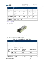
Page 29: ... used for middle and long reach transmission 2 SFP module 1 Appearance Figure1 19 SFP module appearance diagram 2 SFP GbE interface attributes Table1 7 SFP GbE interface attributes Attributes Description Connector type SFP LC Interface standard 802 3 802 3u and 802 3ab Transmit power Typ e Short haul multimode 850nm Optical interface module Medium haul multimode 1310nm Optical interface module Lon...

Page 30: ... 40km 40km 80km Working mode 1000Mbps full duplex mode 3 SFP optical module 1 Appearance Figure1 20 SFP optical module diagram 2 SFP 10GE Ethernet optical interface attributes Table1 8 SFP 10GE Ethernet optical interface attributes Attributes Description Connector type SFP LC Supported physical layer type 10GBASE R Interface rate LAN PHY mode 9 95Gbps 10 5 Gbps Transmis sion power Type Short haul ...

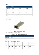
Page 31: ...s full duplex mode 4 XFP optical module 1 Appearance Figure1 21 XFP optical module diagram 2 XFP 10GE Ethernet optical interface attributes Table1 9 XFP 10GE Ethernet optical interface attributes Attribute Description Connector type XFP LC Supported physical layer type 10GBASE R Interface type LAN PHY mode 9 95Gbps 11 1Gbps Transmiss ion power Type Short haul multimode Medium h aul single mode Med...

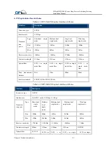
Page 32: ...ode fiber Max transmission distance 300m 10km 40km 80 km 200 km Working mode 1000Mbps full duplex mode 5 QSFP optical module 1 Appearance Figure1 22 QSFP optical module appearance 2 QSFP 40GE Ethernet optical interface attributes QSFP optical module transmission rate is 40Gbps which uses MPO connector Table1 10 QSFP 40GE Ethernet optical interface attributes Central wavelength nm Fiber Mode Fiber ...

Page 33: ... fiber 9 125 μ m single mode fiber 9 125 μ m single mode fiber 9 125μm single mode fiber 9 125 μ m single mode fiber Max transmission distance 2km 15km 40km 80km Interface standard SONET OC 48c SDH STM 64c Table1 12 XFP 10GE POS optical interface attributes Attribute Description Connector type XFP LC Interface rate LAN PHY mode 9 95Gbps 11 1Gbps Transmiss ion power Type Short haul single mode Medi...

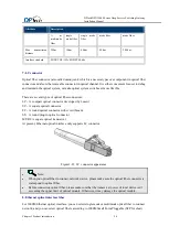
Page 34: ...nnectors LC A compact optical connector developed by Lucent SC A square optical connector FC A round optical connector with screw threads ST A round plug in optical connector MT RJ A square optical transceiver At present Ethernet optical interface only supports LC connector Figure1 23 LC connector appearance Note When you optical fiber to connect network device please make sure the optical fiber c...

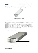
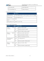
Page 35: ... of power supplies AC power supply and DC power supply which allow user to select according to their real need DPX19000 series products do not support power supplies intermixing DPX19000 A6 series has 4 power module slots which can realize power module N M redundancy DPX19000 A10 series has 8 power module slots which can realize power module N M redundancy DPX19000 A18 series has 12 power module s...

Page 36: ...00W Dimension W D H 102mm 351 mm 41mm AC power supply LED description LED color Status Description 1 Power input LED Green On Means power input is normal Off Means power module isn t inputted Blink Means power input exceed the max range 2 Power output LED Green On Means power module output is normal Off Means power module isn t outputted Blink Means power module input is overload 3 Over temperatur...

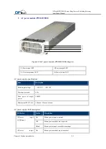
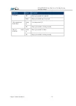
Page 37: ...e LED 4 Power failure LED AC power supply specification Item Description Rated input voltage 48V DC 60V DC Max input current 60A Max power of single power 1800W Dimension W D H 102mm 351mm 41mm AC power supply LED description LED color Status Description 1 Power input LED Green On Means power input is normal Off Means power module isn t inputted Blink Means power input exceed the max range 2 Power...

Page 38: ...Status Description LED Green Off Means power module isn t inputted Blink Means power module input is overload 3 Over temperature LED Yellow Steady on Over temperature LED Off Means power module is working normally 4 Power failure LED Red Steady on Means power module is failure Off Means power module is working normally ...

Page 39: ...ing figure 1 2 3 4 5 6 7 8 1 2 9 10 11 12 13 14 15 16 2 2 Interface numbering method DPX19000 series support multiple kinds of interfaces including CONSOLE port PFP port Ethernet management interface gigabit electrical interface RJ45 gigabit optical interface SFP 10GE optical interface XFP and 10G POS optical interface each of them is configured as interface numbering Except Console port USB port ...

Page 40: ...n to 1 For the same service board interfaces X is same 2 Interfaces on service board are numbering from top to bottom from left to right Y begins from 0 3 Ethernet management interface always is meth0 0 2 3 Interfaces illustration 2 3 1 Service board N 48GET 1 If service board install on slot 1 the eth interfaces are numbering as follows eth1 0 eht1 1 eth1 2 eth1 3 eth1 4 eth1 5 eth1 6 eth1 7 eth1...

Page 41: ...sure that the equipment cabinet and work bench has good ventilation and heat dissipation system Ensure that the equipment cabinet and work bench fastness enough which can support device and installation accessory Ensure that the equipment cabinet and work bench well connected ground To ensure normal operation and long service life of your switch the installation site must meet the requirements in ...

Page 42: ...hen the indoor relative humidity is low electrostatic adsorption is more likely to happen The equipment room must be free of explosion hazards and the electric and magnetic conductible dust as well The contents of the dust must be limited to the values shown in 0 Table3 2 Dust limit in the equipment room Substance Unit Content Dust Particles m 3 104 No visible dust on the table top for three days ...

Page 43: ...otection ground wire to filter electricity power interference by the device filter circuit Keep the device far from the strong power radio launchers radar launchers and high frequency and high current equipment Use electromagnetic shielding when necessary such as you can use shielded cable Require you using interface cable indoors not use it outdoors to prevent overvoltage and over electricity dam...

Page 44: ...le operation In order to meet DPX19000 power supply requirements you should accomplish the following steps 1 Calculate the system power consumption 2 Select power supplies according to the system power consumption and power supply mode To ensure normal operation of the switch make sure the maximum output power of the power supplies is greater than the system power consumption of the switch reserve...

Page 45: ...th of the aisle in the equipment room is at least 0 8 m 2 The equipment room is at least 3 m high 3 Reserve at least 0 8 m of clearance between the rack and walls or other devices 3 3 Required tools 3 3 1 Accessories supplied by the switch Cable wire Grounding wrist Console wire Mount ear Cabling rack Blank panel 3 3 2 User supplied tools and equipment Straight screwdriver Phillips screwdriver Tra...

Page 46: ...nstallation Manual Chapter 4 Device installation 1 Chapter 4 Device installation 4 1 Before installation 1 You have read Chapter 3 carefully 2 The requirements in Chapter 3 are satisfied 3 Power off your device before installation 4 2 Installation Procedure ...

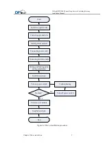
Page 47: ...fic site Install general module Connecting power cord Connecting interface cable Troubleshooting Normal Wiring and binding cable during installation Installation check Turn off power switch Connecting ground wire Yes Start Turn on power switch Select service module Installation check End Figure 4 1 Device installation procedure ...

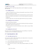
Page 48: ...e are 3 air filter slides on A18 On rear panel the upper right side of rear panel is the air filter slide of the service module L1 L8 and main control slot M1 and M2 The low right side of rear panel is the air filter side of the service module L9 L16 and the screen air intake vent The left lower side is the air filter slide of another screen air intake vent Installation procedures are same as A6 4...

Page 49: ...et According to realistic size of the space you move the device to the proper place Make sure that there is enough space for the device and guide slot which is convenient for you to fix mouthing ear 4 Use pin head screw to mount the device to the cabinet which must be satisfied with the cabinet Maximum size of the pin head screw is not lager than international standard M6 with surface rust proof t...

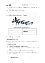
Page 50: ...he safety of operators and equipment anti thunder tamper proof securely ground the switch Make sure the anti interference between the switch chassis and the ground is less than 5 ohm DPX19000 grounding terminal locates at the lower right corner of rear panel with grounding identification Figure 4 2 Grounding wire diagram 1 Rear panel of the chassis 2 Grounding hole screw 3 Grounding identification...

Page 51: ... Connect the ground wire to the ground bar 1 Hex nut 2 Grounding strip 3 Metal wire of the ground cable whose insulation rubber is stripped out 4 Grounding post 5 Grounding bar 4 6 Installing general module 4 6 1 Installing power module Please install AC or DC power supply module according to your selection Please remove the blank panel before you install power supply module 1 Installing AC power ...

Page 52: ...the main control board 1 Operator faces the device front panel 2 Slowly slide main control board into slot along the rail and then press the clip to lock the power supply in position and close the power frame cover 3 Fasten the captive screws on main control board and rotate clockwise by using of Philips screwdriver 4 6 4 Installing the service board Please refer to the main control board installa...

Page 53: ...ctor and supports hot swappable 4 8 Connecting power cords 4 8 1 Connecting AC power cord 1 AC power supply AC power input range 100V AC 120V 200V AC 240V 50 60Hz 2 Ac power socket and appearance AC power module appearance is shown in the following 1 Using single phase three wire power socket with ground connector 2 The earth point of the power socket should well connect to the ground 3 Before you...

Page 54: ...ce and fasten the screws 4 Connecting the other end of the grounding cable to a reliable grounding point 5 Verify power supply LED status on the device front panel Caution Please verify the labels on power cords when you connecting DC power cord 4 9 Verifying the installation Verify that the ground wire is well connected Verify that the configuration cable power input cable are connected correctly...

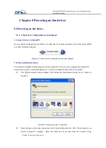
Page 55: ... Figure5 1 Connect device through Console port diagram 2 Setting terminal parameters You should run HyperTerminal program on the terminal PC when you can configure the terminal PC Follow these steps to set terminal parameters on the PC running Windows XP for example 1 The HyperTerminal window displays the Connection Description dialog box as shown in Figure5 2 Figure5 2 Setting up a new connection...

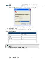
Page 56: ... Figure5 3 setting the serial port used by the HyperTerminal connection 3 Set the serial port parameters Table5 1 describes the details of the serial port parameters shown in Figure5 3 Setting the serial port parameters Properties Value Baud rate 9600 bps the default Data bits 8 Parity check None Stop bits 1 Flow control None Note To restore default parameters click Restore Defaults button ...

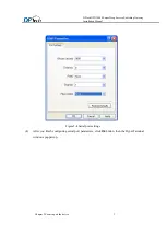
Page 57: ...eep Service Switching Gateway Installation Manual Chapter 5 Powering on the device 3 Figure5 4 Serial port settings 4 After you finish configuring serial port parameters click Ok button then the HyperTerminal windows popped up ...

Page 58: ...allation Manual Chapter 5 Powering on the device 4 Figure5 5 HyperTerminal windows 5 Select File Properties Settings In the Properties dialog box select the Settings tab as shown in Figure 5 6 Select VT100 or Auto detect in the Emulation dropdown menu Click OK ...

Page 59: ...ment of the switch The console cable is correctly connected and the serial port configuration is correct Caution Before powering on the device you should verify the power switch position in case of emergency happened so that you can disconnect the power supply promptly 2 Device power on Turn on device power switch 3 Verification after power on Please do the followings after the device is powered o...

Page 60: ...y and configure if DPtech displayed 5 1 3 Booting procedure Powering on your device PC HyperTerminal displays the device self inspection information Then type in the system password and enter the prompt interface Note There may some differences devices HyperTerminal displayed Use the material object as the standard DPtech DPX19000 A18 device booting information System start booting Booting Basic C...

Page 61: ...138F84 Capacity 1911 6 MB 1 8 GB 3915072 x 512 configuring gmac0 in byte mode 125MHz 1000Mbps full duplex mode B1_XLS416 ATX_I Press Ctrl B to enter extend boot menu conplat will boot in 3 please enter the password Note Here the default password is DPTECH 5 2 Default Web login method DPX19000 Series product allow administrator login through web management interface The default IP address is 192 16...

Page 62: ...ation Manual Chapter 5 Powering on the device 8 Figure5 7 WEB management interface Caution We do not suggest you that use both of the http and https protocol to login on the same PC We recommended you that you should modify the default password after first login ...

Page 63: ... switch is turned on 4 Verify the power cord is correct 5 Verify the power voltage is in accordance with device requirement Caution Please do not plug out power cord if the device is still running If you execute the above verification the power LED is still off please contact sales agent to solve the problem 6 2Main control board failure 1 Main control board MPU LED red Fault phenomenon Main contr...

Page 64: ... is normal 2 If device power on is normal please check whether the service board is inserted in slot correctly 3 If service board is inserted in the slot correctly means the service board is failure If the above failure still exists please record the information and contact sales agent 6 4 Switching network board failure 1 Switching network board Fabric LED off Fault phenomenon Switching network b...

Page 65: ...s the old fan tray fails If the above failure still exists please record the information and contact sales agent 6 6 Configuration terminal problems If the configuration environment setup is correct the configuration terminal displays booting information when the device is powered on If the setup is incorrect the configuration terminal displays nothing or garbled text 1 No terminal display Fault p...

Page 66: ...Troubleshooting 4 If terminal display is garbled after you power on the device Troubleshooting Please verify the HyperTerminal parameters Baud rate 9600 Data bits 8 Parity none Stop bits 1 Flow control none Emulation VT100 If these parameters are not correct please configure them again ...

Page 67: ...Chapter 6 Troubleshooting 1 ...

Reviews: