DPtech LSW5003 Series Industrial Ethernet Switch Installation Manual
Chapter 3 Device Installation
5
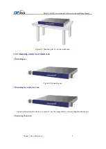
Figure3-5
Fasten the switch
3.4 Connecting grounding wires
!
Caution
:
When installing or using your switch, properly connect the grounding wire for lightning protection
and anti-interference.
The grounding resistance must be smaller than 5 ohm.
Generally, the equipment cabinet provides a row of grounding bar and equipment room also provide
grounding row, which allow you to connect the switch grounding wire to the equipment cabinet
grounding bar or to grounding row.
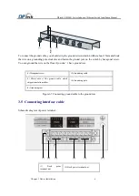
(1) Grounding hole
(2) Grounding sign
(3) OT terminal (4)
(4) Grounding cable
(5) Grounding screw
Figure3-6
Diagram for connecting grounding wire
Connecting grounding cable method:
(1) Remove the grounding screw on the rear panel of the switch.
(2) Attach the OT terminal on the grounding cable to the grounding screw on the chassis.
(3) Fasten the grounding screw, which is attached with the OT terminal of the grounding cable, into the
(4) Grounding screw hole with a screwdriver.
Connect the other end of the cable to the ground.

