DPtech LSW5003 Series Industrial Ethernet Switch Installation Manual
Chapter 3 Device Installation
7
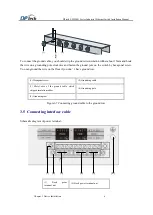
(3)
Power
terminal
PWR0
(4) Power terminal PWR1
(5) Alarm terminal
(6) earth terminal
3.5.1 Hardware power failure alarm
3.5.5.1 Hardware power failure alarm
The device reserves the external hardware alarm terminals: as shown below, Relay alarm output
Warning port Description: C: connect public terminal; NO:not open; NC:not connect
Alarm terminal: 3-core 5.0mm connecting terminal
Alarm output rated load: AC:, 250V, 8A, DC:, 30V, 8A
3.5.5.2 Alarm wiring method
State event
:
Event 1
:
The device works normally, the double power supply works normally, and the alarm terminal
C (9) closes with NO (8),C (9) is disconnected from NC (10)
Event 2
:
The device operates normally, one of the power supplies is switched off, and the alarm
terminal C (9) is disconnected from the NO (8),C (9) closes with NC (10)
Event 3
:
Abnormal operation of device, double power failure, alarm terminal C (9) is disconnected
from NO (8) ,C (9) closes with NC (10);
Warning device: such as warning light, alarm buzzer, warning device.
3.5.2 Connecting AC power cable
1.AC power
AC power input range
:
100V-240V AC, 50/60Hz
2.Method for connecting AC power cable
(1) Ensure that the protection grounding wire has been correctly connected to the earth, and check the
voltage value of each pin (pictured above). The L is connected with a power supply live Wire, N is
connected with zero line,
grounding earth.
(2) User make the power supply terminal according to the meaning of each pin. Then user insert one
end of the AC power cable into the AC power supply terminal of the device, and plug the other end into
the external AC power socket
(3) Check the status of the front panel power indicator PWR of the device
3.5.3 Connecting DC power cable
1.DC power
DC power input range
:
100V-240V DC

