DPtech LSW5602 Ethernet Switch Installation Manual
Chapter 3 Device Installation
3-9
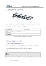
Figure3-8
Diagram for the power cord connection
(
take LSW5602-44GTGGC as example
)
3.6.2
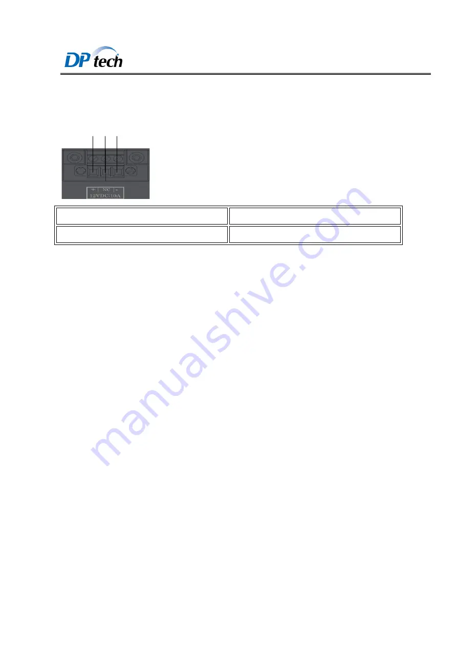
Connecting Redundancy Power Cable
(
1
) (
2
) (
3
)
(1) Power positive (+)
(2) Power NC
(3) Power negative (-)
The input power of the switch is direct current 12V. Lead foot of the device as shown in the above image.
Please connect the attaching plug according to all lead foot.
Note
:
Before power on your switch, you should connect your switch to the ground and well connect ground and
wiring the cables separately will benefit for the anti-interference, so that it can ensure the device working
normally.
Verify the voltage value and pin before you connect power on the switch avoid mistake.
3.7 Verify the Installation
The ground wire is securely connected.
Both of the console cable and power cord are correctly connected.
All the interface cables are routed indoors. If there are cables outdoors, check that the socket strip with
lightning protection and lightning arresters for network ports have been correctly connected

