background image


DPtech LSW5602 Ethernet Switch Installation Manual 


Chapter 3 Device Installation 

3-7 


the grounding screw hole with a screwdriver. 

(4)


Connect the other end of the cable to the ground. 

(1)

(2)
(3)
(4)

(5)


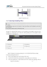
To connect the ground cable, you should strip the ground wire insulation rubber about 15mm and hook 

the  wire  on  a  grounding pole  clockwise and fasten the  ground pole  on the switch by hexagonal screw. 

You can ground the wire on the floor if you don’t have ground row. 


(1) Hexagonal screw 

(2) Grouding cable  

(3)  Metal  wire  of  the  ground  cable  which  stripped 

insulation rubber 

(4) Grouding pole 

(5) Grouding row 


Figure3-7


Connecting ground cable to the ground row 


3.5  Connecting Interface Cable 

3.5.1  

Connecting Configuration Port Cable 

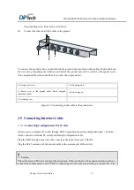
Allows you to configure the switch through RS232 asynchronous serial configuration port

Console

which connect to terminal PC serial port through configuration cable. 

Plug the DB-9 female connector of the console cable to the serial port of the PC. 

Plug the RJ-45 connector of the console cable to the console port of the switch. 


  Caution


The serial ports on PCs do not support hot swapping. If the switch device has been powered on, always 
connect the console cable to the PC before connecting it to the switch, and when you connect PC to the 

Summary of Contents for LSW5602 Series

Page 1: ...DPtech LSW5602 Ethernet Switch Installation Manual i DPtech LSW5602 Ethernet Switch Installation Manual...

Page 2: ...es full range technical support If you need any help please contact Hangzhou DPtech Technologies Co Ltd and its sale agent according to where you purchase their products Hangzhou DPtech Technologies C...

Page 3: ...d by any means Owing to product upgrading or other reasons information in this manual is subject to change Hangzhou DPtech Technology Co Ltd has the right to modify the content in this manual as it is...

Page 4: ...PORT 1 19 1 4 2 10 100 1000BASE T ETHERNET ELECTRICAL INTERFACE 1 20 1 4 3 SFP INTERFACE 1 21 1 4 4 COMBO PORT 1 24 1 5 INSERT CARD MODULE 1 25 1 5 1 INTERFACE BOARD LSW 1XGES 1 25 1 5 2 INTERFACE BOA...

Page 5: ...3 5 3 CONNECTING SERVICE PORT 3 8 3 6 CONNECTING POWER CABLE 3 8 3 6 1 CONNECTING ALTERNATING POWER CABLE 3 8 3 6 2 CONNECTING REDUNDANCY POWER CABLE 3 9 3 7 VERIFY THE INSTALLATION 3 9 CHAPTER 4 STAR...

Page 6: ...24 Figure1 21 Front View of the DPtech LSW 1XGES 1 25 Figure1 22 Front view of the DPtech LSW 2XGES switch 1 27 Figure1 23 DPtech LSW 2XGES operation status indicator 1 28 Figure1 24 Front view of th...

Page 7: ...DPtech LSW5602 Ethernet Switch Installation Manual ii Figure4 7 Web management interface 4 8...

Page 8: ...butes of the GbE optical interface 1 21 Table1 4 Relationship between two ports 1 24 Table1 5 10GE Ethernet optical interface attributes 1 26 Table1 6 GbE interface attributes 1 30 Table1 7 GbE interf...

Page 9: ...n At present the DPtech LSW5602 series commercial switches includes the followings LSW5602 44GT4GC LSW5602 16GT8GC LSW5602 16GP8GC LSW5602 44GT4GC PWR LSW5602 16GT8GC PWR The specification of DPtech L...

Page 10: ...ts 10GE SFP interface module expansion card LSW 2XGES Single port 10GE SFP interface module expansion card LSW 1XGES Input voltage Alternating current Rated voltage range 100V 240V AC 50 60H RPS input...

Page 11: ...and optical port are forming Combo port Note only one port can be used when two Combo ports are forming at the same time Supporting interface module There are two interface module on the rear panel o...

Page 12: ...midity non condensation 10 95 1 3 Front Panel and Rear Panel of the Switch 1 3 1 Product appearance of the LSW5602 44GT4GC switch 1 3 1 1 Front view 8 1 2 3 4 5 7 6 9 10 11 12 13 1 10 100 1000M ethern...

Page 13: ...ectrical interface 1 is sending and receiving data packet Off Means electrical interface 1 is in disconnection status 5 Power LED PWR Green On Means the power supply is working normally Fast flashing...

Page 14: ...s failed Slow flashing 1Hz Means as configuration single board is running with normal working status Fast Flashing 8Hz Mean software is loading or single board is starting 10 System LED RUN Green Slow...

Page 15: ...identification 7 Grounding terminal Figure1 3 LSW5602 44GT4GC rear view 1 3 2 Product appearance of the LSW5602 44GT4GC PWR switch 1 3 2 1 Front view 8 1 2 3 4 5 7 6 9 10 11 12 13 1 10 100 1000M ether...

Page 16: ...10 100 1000M Ethernet electrical interface LED 1 Green On Means electrical interface 1 is in connection status Blinking Means electrical interface 1 is sending and receiving data packet Off Means elec...

Page 17: ...1 isn t inserted recognizable module or the inserted module is failed Slow flashing 1Hz Means as configuration single board is running with normal working status Fast Flashing 8Hz Mean software is lo...

Page 18: ...GC PWR rear view 1 3 3 Product appearance of the LSW5602 16GT8GC switch 1 3 3 1 Front view 1 2 3 8 7 9 10 11 12 13 5 4 6 1 10 100 1000M Ethernet electrical interface LED 0 2 10 100 1000M Ethernet elec...

Page 19: ...sconnection status 6 Power LED PWR Green On Means power supply is working normally Fast flashing 8Hz Means the power supply has failed Off Means the power supply is absent 7 Slot LED SLOT 0 On Means t...

Page 20: ...as your configuration which is in normal status Fast flashing 8Hz Means system is loading software or the board is starting Off Means no power has inputted or the board isn t working 12 1000M Ethernet...

Page 21: ...ctrical interface 0 3 10 100 1000M Ethernet electrical interface LED 1 4 1000M Ethernet optical interface 16 5 CONSOLE port 6 AC power supply LED PWR 7 Slot LED SLOT 0 8 Virtual switching matrix LED V...

Page 22: ...normal status Fast flashing 8Hz Means the module in slot 0 is loading software or the board is starting Off Means no recognizable module inserted in slot 0 or the inserted module is failed 8 Virtual s...

Page 23: ...optical port 17 is transmitting data Off Means GE optical port 17 is in disconnection status 13 1000M Ethernet optical interface LED 16 Green On Means GE optical port 16 is in connection status Flashi...

Page 24: ...r supply LED PWR 1 12 1000M Ethernet optical interface LED 0 13 1000M Ethernet optical interface LED 1 Figure1 13 LSW5602 16GP8GC front view 2 4 6 7 8 13 12 11 10 9 LED Status Description 2 10 100 100...

Page 25: ...N Green Slow flashing 1Hz Means the board is working as your configuration which is in normal status Fast flashing 8Hz Means system is loading software or the board is starting Off Means no power has...

Page 26: ...LSW5602 16GP8GC front panel LED 1 3 5 2 Rear view 1 2 3 4 5 6 7 1 AC power supply socket 2 AC power supply socket 3 Slot SLOT 0 4 Slot SLOT 1 5 Bar code area for the device 6 Groudning identification...

Page 27: ...or RJ45 Port MDI MDIX autosensing Frame format Ethernet_II Ethernet_SNAP Rate and duplex mode 10 Mbps autosensing Half full duplex auto negotiation 100 Mbps autosensing Half full duplex auto negotiati...

Page 28: ...gh cable The sequences of the twisted pairs crimped in the RJ 45 connectors at both ends are the same It connects a terminal device PC or router to a HUB or LAN Switch A standard cable is provided for...

Page 29: ...de fiber 9 125 m single mode fiber 9 125 m single mode fiber Max transmission segment 0 55km 15km 40km 40km 80km Operating mode 1000Mbps Full duplex 1 4 3 2 Fiber connector A fiber connector moveable...

Page 30: ...tical receive power of the transceiver module Otherwise the transceiver module maybe damaged 1 4 3 3 Optical Fiber For Connecting Ethernet Optical Interface For 1000M Ethernet optical interface you ca...

Page 31: ...an be used when Combo port form at the same time The relationship between two ports are Table1 4 Relationship between two ports Product Model 1000Base X SFP Port 10 100 1000Base T Ethernet Port LSW560...

Page 32: ...interface 1 2 3 4 5 1 10GE ethernet optical interface 0 2 10GE optical interface data transceiving status indicator ACT 0 3 10GE optical interface link status indicator light LINK 0 4 Spring screw 5...

Page 33: ...rd LSW 1XGES has a SFP 10GE Ethernet optical interface SFP port indicator light at the right side of the SFP Connector the indicator light means corresponding SFP interface current status Table1 7 10G...

Page 34: ...E ethernet optcial interface 0 2 10GE optical interface transceevig status indicator ACT 0 3 10GE optical interface link status indicator light LINK 0 4 10GE ethernet optical interface 1 5 10GE optica...

Page 35: ...data Off Means port 0 isn t transceiving data 6 10GE SFP optical interface link status indicator light LINK 1 On Means port 1 has created connection Off Means port 1 hasn t created connection 5 10GE S...

Page 36: ...tical interface data transceiving status indicator light ACT 0 3 1000M optical interface link status indicator light LINK 0 4 1000M etherent optical interface 1 5 1000M optical interface data transcei...

Page 37: ...LINK 1 On Means port 1 has created connection Off Means port 1 hasn t created connection 5 1000M SFP optical interface transceiving status indicator light ACT 0 Blinking Means port 1 is transceiving...

Page 38: ...de fiber Max transmission distance 0 55km 15km 40km 40km 80km Operating mode 1000 Mbps full duplex 1 5 4 Interface Board LSW 2XCX4 1 5 4 1 Introduction to the Interface Board LSW 2XCX4 LSW 2XCX4 is th...

Page 39: ...nnection 2 1000M SFP optical interface transceiving status indicator light ACT 0 Blinking Means port 0 is transceiving data Off Means port 0 isn t receiving data packet 6 1000M SFP optical interface l...

Page 40: ...ty 17dBm 20dBm 23dBm 21dBm 22dBm Central wavelength 850nm 1310nm 1310nm 1550nm 1550nm Optical fiber 62 5 125 m multimode fiber 9 125 m single mode fiber 9 125 m single mode fiber 9 125 m single mode f...

Page 41: ...14 9 10 100 1000M Ethernet Electrical Interface 16 10 10 100 1000M Ethernet Electrical Interface 18 11 10 100 1000M Ethernet Electrical Interface 20 12 10 100 1000M Ethernet Electrical Interface 22 13...

Page 42: ...l Interface 29 40 10 100 1000M Ethernet Electrical Interface 31 41 10 100 1000M Ethernet Electrical Interface 33 42 10 100 1000M Ethernet Electrical Interface 35 43 10 100 1000M Ethernet Electrical In...

Page 43: ...pation system Ensure that the equipment cabinet and work bench fastness enough which can support device and installation accessory Ensure that the equipment cabinet and work bench well connected groun...

Page 44: ...When the indoor relative humidity is low electrostatic adsorption is more likely to happen The equipment room must be free of explosion hazards and the electric and magnetic conductible dust as well...

Page 45: ...system coupling To resist the interference make sure to The alternating power supply system is TN system Adopt single phase three wire socket with protection ground wire to filter electricity power in...

Page 46: ...es the cables should be straight not curved or not twined You should bundle the cables if there are too many cables and according to different types to bundle the cables such as power line interface w...

Page 47: ...l Chapter 3 Device Installation 3 1 Chapter 3 Device Installation 3 1 Installation Preparation You have read Chapter 2 Preparation for Installation carefully The requirements in Chapter 2 are satisfie...

Page 48: ...DPtech LSW5602 Ethernet Switch Installation Manual Chapter 3 Device Installation 3 2 3 2 Installation Procedure...

Page 49: ...al Verify the installation Power on your switch Toubleshooting Normal Connect the power cord Verify the installation End Start Power off the switch Install switch to a 19 inch rack Mount the switch on...

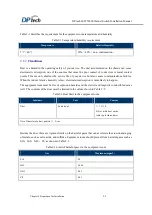
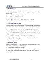
Page 50: ...ll your switch to the working bench Install your switch to the 19 inch equipment cabinet 3 3 1 Mounting Switch on Workbench If a standard 19 inch rack is unavailable you can place the switch on a clea...

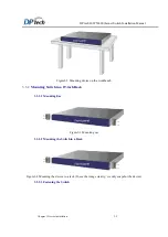
Page 51: ...igure3 2 Mounting device on the workbench 3 3 2 Mounting Switch in a 19 inch Rack 3 3 2 1 Mounting Ear Figure3 3 Mounting ear 3 3 2 2 Mounting the Switch in a Rack Figure3 4 Mounting the device to a r...

Page 52: ...ment room also provide grounding row which allow you to connect the switch grounding wire to the equipment cabinet grounding bar or to grounding row 1 2 3 4 5 1 Grounding hole 2 Grounding sign 3 OT te...

Page 53: ...hich stripped insulation rubber 4 Grouding pole 5 Grouding row Figure3 7 Connecting ground cable to the ground row 3 5 Connecting Interface Cable 3 5 1 Connecting Configuration Port Cable Allows you t...

Page 54: ...twisted pair cable to ensure electromagnetic compatibility Note The switch doesn t provide any twisted pair cable Prepare it yourself Connect network management port to the terminal computer netword...

Page 55: ...re power on your switch you should connect your switch to the ground and well connect ground and wiring the cables separately will benefit for the anti interference so that it can ensure the device wo...

Page 56: ...on the switch and connect the DB 9 female connector of the console cable to the serial port on the PC that is used for configuring the switch as shown in Figure4 1 Figure4 1 Network diagram for config...

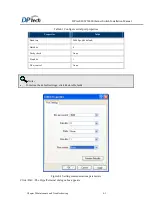
Page 57: ...nd click OK The dialog box as shown in Figure 4 3 displays Select the serial port to be used from the Connect Using dropdown menu The serial port must be the same port connected by the console cable F...

Page 58: ...ble4 1 Configure serial port properties Properties Value Baud rate 9600 bps the default Data bits 8 Parity check None Stop bits 1 Flow control None Note To restore the default settings click Restore D...

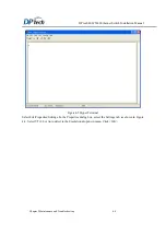
Page 59: ...l Chapter 5 Maintenance and Troubleshooting 4 4 Figure4 5 Hyper Terminal Select File Properties Settings In the Properties dialog box select the Settings tab as shown in Figure 4 6 Select VT100 or Aut...

Page 60: ...terminal has been started and the related parameters have been set on it Caution Before powering up the switch please verify the power switch position of the switch When danger happens you can power...

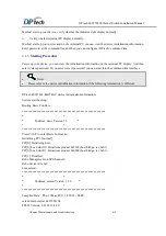
Page 61: ...password If you enter correct password you can enter into the command line interface Note Please refer to the device initialization information if the following information is different DPtech LSW5602...

Page 62: ...lat system will back to extend menu please enter the password Password Note By default the syetem password is DPTECH 4 2 Default Login Method for Web LSW device support Web management function the def...

Page 63: ...ance and Troubleshooting 4 8 Figure4 7 Web management interface Caution You should not login to the web management interface by using of http or https protocol on the same PC After first time you logi...

Page 64: ...rify whether the power wire is correct 5 Verify the power supply voltage correspond to the switch Caution Do not hot plug power wire Exam the above steps if power indicator light is still not on pleas...

Page 65: ...tion is VT100 If your configuration is not same with the above parameters reconfigure the configuration 5 2 2 Garbled characters on the terminal Trouble phenomenon See the garbled characters on the te...

Reviews: