background image

24

english

Ventilation of the Solarium

The ventilation system employed in your new solari-

um is the best possible.   Cool air is drawn into vents at

the base of the unit.

The strongest ventilation is at the bench acrylic area.

With the strong air circulation, dust will be carried into

the  solarium  and  deposited  onto  its  internal

components. Any accumulation of dust will hinder the

ventilation efficiency of the main fans. For this reason

the solarium should be cleaned on a regular basis.

Bear in mind that cool air can reduce the temperature

of this machine better than warm air. Insure that the

room in which the solarium is operated is sufficiently

supplied with cool, fresh air.

Cleaning the Solarium

Disconnect the power from the machine before each

cleaning.  Use only a moist cloth during cleaning.

Cleaning of the Acrylic Glass Sheets

Under heavy air circulation, as described above, dust may

collect on the inner sides of the acrylic glass sheets. This

may occur all over the sheets or at localised areas. In this

case,  the  acrylic  glass  sheet  must  be  removed  and

cleaned, as described above under "Replacing the lamps".

Use  only  solvent-free,  non-aggressive  household

cleaning agents for cleaning the glass sheets.

Such dust contamination can also occur with new units

after only a short time in operation. This is due to the varying

static charging of the acrylic glass sheets.

This  cleaning  work  is  not  covered  by  the  guarantee

conditions.

Facial lamps operate at very high temperatures and

are cooled with fans in the cassettes. The lamp function

is controlled additionally by a heat sensor. Should a

fan stop working in any cassette the relay will turn the

unit off automatically. The face tanner may not be used

until an authorised service representative has repaired

the problem. Automatic emergency shut offs of this

type occur rarely. The cassette fans in the facial tanners

rarely fail.

Only factory - original components and spare parts

may be used in servicing this solarium.

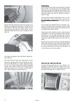
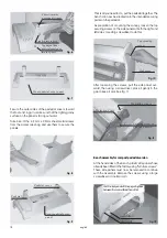
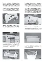
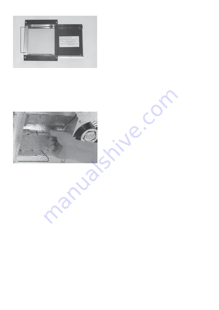
The filter and lower safety plate can be removed from the

cassette for cleaning, see Fig. 38. When refitting the plate,

always ensure that the filter plate is inserted facing upward,

i.e. toward the face-tanner. To ensure this is done correctly,

you should mark the plate accordingly when removing it,

and then refit it in the same way.

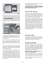
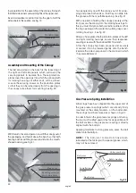
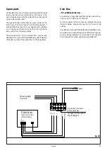
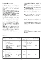
To change the metal halogen lamp, grasp the lamp at one

of the flattened ends, and push approximately in the

lengthwise direction in order to remove it from the holder,

see Fig. 39.

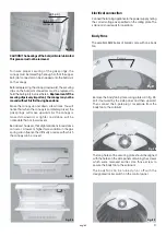
The new lamp is inserted in the same way. Ensure that

you do not touch the actual glass of the lamp. Any marks

or fingerprints on the lamp should be cleaned off with

pure alcohol or white spirit.

NEVER  USE  A  FACE  TANNER  WITH  BROKEN  OR

CRACKED  FILTER  GLASSES!  Doing  so  will  cause

damage to eyes and facial skin.

Fig. 38

Remove 

these 

2

screws

Fig. 39

Thermal fuse

Summary of Contents for excellent 24/1

Page 1: ...1 IP 20 Gebrauchsanweisung Manual D GB excellent 24 1 24 7 28 1 28 9 30 3 32 3 Druck Nr 29492628 16 06 20013084...

Page 2: ...hlgebl sen d rfen nicht abgedeckt werden da sonst eine berhitzung des Ger tes eintritt l Bei einem L fterausfall die Folge ist eine ungew hn liche Erw rmung des Ger tes sofort das Ger t aus schalten l...

Page 3: ...eMedikamenteeinnehmen sprechenSievorher mit Ihrem Arzt Einige Medikamente k nnen die Wir kung des UV Lichtes verst rken und es besteht das Risiko von Hautsch digungen l Entfernen Sie gr ndlich alle Ko...

Page 4: ...b 2 diese Schrauben nicht l sen Abb 3 Fu befestiguns schauben Abb 4 Profilleiste Ger tevorderseite Abb 5 Blech Treibschraube Profilleiste Beachten Sie dass die offene Seite der Nut nach unten zeigt Ab...

Page 5: ...e Befestigungsschrauben f r Sicherungslasche Abb 11 diese Schraube nicht l sen Als Vorbereitung f r die Montage des Oberteils l sen Sie jeweils links und rechts die zwei oberen Befestigungs schrauben...

Page 6: ...so den seitlichen Ab stand der Fu blenden sicherstellen Abb 15 Fu blende Fu blende untere Nut im L ngsholm obere Nut in der Bodenleiste Zwischen die Fu blenden montieren Sie zum Abschlu der Liegenmon...

Page 7: ...Gasdruckfeder Montage An den Gasdruckfedern diese sind bereits an den Sicherungslaschen fest montiert sind am oberen Ende an der Kugelpfanne Sicherungsringe eingeclipst Diese Ringe m ssen wie in Abb 2...

Page 8: ...te Abweichungen be stehen k nnen Eine geringe Druckabweichung in der Gasdruckfeder kann unter Umst nden die Schwenkbe wegung etwas beeinflussen Abb 26 Elektroanschluss Nach dem Elektroanschluss hierzu...

Page 9: ...e an der hinteren L ngsseite an mehreren Stellen et was nach unten bei gen gendem Druck wird die Scheibe mit dem Einfassprofil in die Nut des L ngsholms ein schnappen Abb 34 Abb 32 L ngsholm Einfa pro...

Page 10: ...derStarterunterleich tem Druck und einer Linksdrehung herausgenommen Den neuen Starter leicht in die Fassung eindr cken und nach rechts bis zum Anschlag drehen Bei dem Oberteil ist die Acrylscheibe mi...

Page 11: ...ier die unterschiedliche statische Aufladung der Acrylscheibe Diese Reinigungsarbeiten sind nicht in der Garantie Ge w hrleistung enthalten Die Lampe des Gesichtsbr uners wird bei normalem Be trieb se...

Page 12: ...en nur M nz automaten mit integriertem L fternachlauf verwendet werden Abb 40 M nzautomat PE N L1 NC Netzanschluss M nzer 3N AC 400 V Timer N L Anschluss M nzer Br cke entfernen M nzer lt Plan anschli...

Page 13: ...lgen wenn der M nzer abgeklemmt ist und die Drahtr cke L1 Zeit montiert ist sie he Anschlussplan Abb 40 F r diesen Vorgang werden 2 Personen ben tigt l Trennen Sie die Anlage komplett vom Netz l W hre...

Page 14: ...hen Bestimmungen bernommen Herstellergarantie Die Garantiezeit beginnt mit dem Datum des Kauf belegs und dauert grunds tzlich 12 Monate Garantieleistungen erfolgen nur dann wenn der zum Ger t geh rige...

Page 15: ...ered to avoid overheating of the tanning appliance l In case of fan failure which results in unusual heating of the tanning appliance turn the equipment off immediately l It is possible that lamps wil...

Page 16: ...ltraviolet exposure radiation from the sun or from UV appliances can lead to damage to the skin or eyes These biological effects depend on the type and quantity of exposure radiation as well on the se...

Page 17: ...front of the feet Use two 4 2 mm x 9 5 mm sheet metal screws do this Screws to secure the pedestal feet Profile strip Machine front Fig 4 Profile Strip Fig 5 Sheet metal screw Situate the top edge of...

Page 18: ...rd the foot end Again make sure that the lightly grainy surface on the panel is facing outward Take 3 ea of the 4 2 mm x 9 5mm sheet metal screws from the accessories bag and use them to secure the pa...

Page 19: ...tance of the foot panels Fig 15 Foot panel Floor panel Lower groove in lengthwise spar Upper groove in floor rail To complete the assembly of the bench now fit the front foot panel between the other t...

Page 20: ...l grease which may not be removed Fig 22 Screw in solidly Rotatinghousing Protection plate After the canopy has been properly and securely mounted it can be lowered gently onto the bench Replace the s...

Page 21: ...y not be moved without this first having been done Move the canopy up and down a few times You will notice that when the canopy is completely raised the gas springs will move upwards As the canopy is...

Page 22: ...ly downward and pulled forward with uniform pressure The acrylic pane is then released along the rear side and can be removed from the recliner Please note The acrylic pane expands under the influende...

Page 23: ...the sheet to take on the form of the canopy Fig 27 Fig 26 Press th mounting profile slightly downwards Fig 25 Now press the pane and the mounting profile slightly downward at several points along the...

Page 24: ...evarying static charging of the acrylic glass sheets This cleaning work is not covered by the guarantee conditions Facial lamps operate at very high temperatures and are cooled with fans in the casset...

Page 25: ...ur appliance is indicated on an appliance sticker in the back on the right hand side next to the connecting cable These spare parts can be ordered from your service departmentoryourauthoriseddistribut...

Page 26: ...perated After release by the coin box the timer is going from 0 minutes upwards The appliance can be started and stopped The up and down buttons are locked The other buttons keep their function When t...

Page 27: ...e packaging caution danger of transport damage to our service department Always include the completed warrenty certificate when returning equipment Possible shipping costs arising from the transport t...

Page 28: ...28 Notizen notes...
Reviews: