26
l
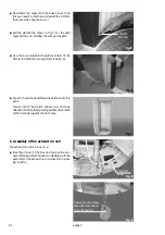
The full length of the lower bearing of the door now
must be lifted onto the hinged panel (fig. 14).
l
Swivel the door segment until the upper bearing is
located in the slotted hole of the exhaust air unit
(fig.15).
l
To bolt the assembly remove from the accessories
bag the upper hinged panel and 2 socket head
screws M10x30 (fig. 16).
The door segment can be adjusted by the hinged
panel on top of the unit.
5. Electric installation
l
The wiring of the segments to the operating unit,
located on top of the exhaust unit, is made in
accordance with figures 17, 18a and 18.
Fig. 14
Fig. 15
Fig. 16
Upper bearing
DIN 912 M10x30 2
screws
Upper hinged panel
À
Main cooler
Á
Air conditioning system
Â
Main power connection
Ã
Door segment
Ä
Left tanning segment
Å
Right tanning segment
Æ
Body cooler
Ç
Switch of cooler
È
Coin box
É
Remote start enable signal
Connection: Session counter
Illumination lighting
Illumination lighting for
changing room
Fig. 17
1
2
3
4
5
6
7
8
9
10
12
11
13
11
12
13
english


