background image

CONTACT US AT 

www.DRpower.com

          3


Chapter 1:  Important Safety Considerations 

We want you to enjoy years of safe and productive use from your DR 2-CYCLE TILLER CULTIVATOR.  We do not want you injured, 
so please take a few moments to read the following instructions for safely operating your new Tiller/Cultivator. 

Your DR 2-CYCLE TILLER CULTIVATOR carries  prominent safety labels (shown below) to remind you of important information 
while you are operating the machine.  Take a moment to study these labels before you operate the machine.  Please, immediately 
replace labels if they should become unreadable due to fading, or otherwise damaged during use of your DR 2-CYCLE TILLER 
CULTIVATOR. 


Protecting Yourself and Those around You 

Tragic accidents can occur if the operator is not alert to the presence of children.  Children are often attracted to the 
Tiller/Cultivator and the activity of tilling.  Never assume that children will remain where you last saw them.


This tilling machine, can cut, and sever parts of your body if they become in contact with the moving Tines.  Always take the 
following precautions when operating the DR 2-CYCLE TILLER CULTIVATOR: 


Only allow responsible individuals who have a thorough understanding of these instructions to operate the Tiller/Cultivator.  
Never allow children to operate the machine. 


Always wear protective goggles or safety glasses with side shields while tilling to protect your eyes from possible foreign objects 
thrown from the machine. 


Wear shoes with non-slip treads when using this machine.  If you have safety shoes, we recommend wearing them.  Do not use 
the machine while barefoot or wearing sandals with exposed toes or heels. 


Avoid wearing loose clothing or jewelry, which can catch on the machine’s moving parts. 


We recommend wearing long pants and gloves while using this machine.  Be sure the gloves fit properly and do not have loose 
cuffs or drawstrings. 


Never place your hands, feet, or any part of your body near the Tines when starting the Engine or while the DR 2-CYCLE TILLER 
CULTIVATOR’s Engine is running. 


Keep children, other bystanders, and pets away from your work area at all times.  Stop the Engine when another person or pet 
approaches. 


Before and while pulling the machine backwards, look behind and down for small children and for secure footing.   


We recommend the use of ear protectors or earplugs rated for at least 20 dba to protect your hearing. 

#A0001077239 

#A0001077298 

Summary of Contents for PILOT 2C

Page 1: ...instructions before operating the DR 2 CYCLE TILLER CULTIVATOR DR Power Equipment Toll free phone 1 800 DR OWNER 376 9637 Website www DRpower com DR 2 CYCLE TILLER CULTIVATOR SAFETY OPERATING INSTRUC...

Page 2: ...or technical assistance please visit our website at www DRpower com or call Toll Free 1 800 DR OWNER 376 9637 and one of our Technical Support Representatives will be happy to help you We also hope to...

Page 3: ...ng the DR 2 CYCLE TILLER CULTIVATOR Only allow responsible individuals who have a thorough understanding of these instructions to operate the Tiller Cultivator Never allow children to operate the mach...

Page 4: ...as Store all fuel and oil in containers specifically designed and approved for this purpose and keep away from heat open flame and out of the reach of children Mix the oil and gasoline outdoors and th...

Page 5: ...nd utilities including water lines gas lines electric cables or pipes Do not operate the machine on terrain soil with large rocks and foreign objects which can damage the equipment The tines of the cu...

Page 6: ...ll be happy to help you DR 2 CYCLE TILLER CULTIVATOR Specification Sheet Engine Single Cylinder 2 Cycle Air Cooled Engine Speed 9000 rpm Displacement 43cc Bore Stroke 40 34 mm Power Output 1 34 HP Max...

Page 7: ...than your machine Figure 1 Throttle Control Lever 43cc 2 Cycle Engine Manual Recoil Start Handle Fuel Cap Primer Bulb Choke Lever Tine Shield 2 Position Tool Less Handlebar Height Adjustment Left Hand...

Page 8: ...h Throttle Lever and Left Handlebars to the Middle Handlebar using the remaining two T Handle Nuts two Handle Clamp Bolts and two Curved Washers Figure 3 DO NOT over tighten the T Handle Nuts 4 Secure...

Page 9: ...e area around the Fuel Tank Cap and remove it slowly placing the Cap on a clean dry surface Figure 5 2 Carefully fill the Fuel Tank to avoid spilling to approximately 1 below the bottom of the Fill Ne...

Page 10: ...er Rope again 4 After the Engine starts release the Throttle Lever and move your left hand to the Handlebar position for stability Slowly push the Choke Lever to the half choke position with your righ...

Page 11: ...previous section 3 Lift Tines off the ground and operate the Throttle Lever to full speed 4 Slowly lower the Tines into the soil as you begin walking forward to till soil Note Holding back on the Han...

Page 12: ...position and then release the Locking Sleeve until it locks into one of the three cutouts in the Vertical Guide Adjusting the Drag Stake The Drag Stake is used to help regulate tilling depth and cont...

Page 13: ...ition of the machine e g nuts bolts welds etc Clean Engine Exterior Cooling Fins Clean Air Filter Check Tines for Wear Replace Air Filter Replace Spark Plug Cover the Engine Muffler Carburetor and Air...

Page 14: ...ice Tools Recommended Feeler Gauges Wire Brush Spark Plug Wrench Spark plug gap must be correct for efficient operation Proceed as follows to service the spark plug 1 Clean area around spark plug Boot...

Page 15: ...Locknut that secures the right side Tine Assembly to the Shaft using two 13mm Wrenches Figure 16 2 Remove the Bolt and Locknut that secures the left side Tine Assembly to the Shaft using two 13mm Wre...

Page 16: ...rtially in the CHOKE position place in the RUN position The Fuel Filter in the Fuel Tank may be clogged clean or replace the filter If your Engine still lacks power visit our website at www DRpower co...

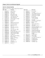
Page 17: ...ng Thrust 26 A0000967157 Reducer Thrust Bearing 27 A0000967158 Shaft Worm 28 A0000967106 Hex Bolt M8 X 40 29 A0000967159 Tine Left 30 A0000967107 Nut M8 Metal Lock 31 A0001077337 Shield Tine Ref Part...

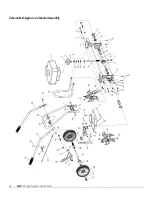
Page 18: ...18 DR 2 CYCLE TILLER CULTIVATOR Schematic Diagram Cultivator Assembly...

Page 19: ...ed by the manufacturer s owner s manuals The warranty holder is responsible for replacement of normally wearing parts such as the Tines Tine Hardware Throttle Lever Spark Plug Air Filter and Wheels At...

Page 20: ...ate amount of stabilizer or fuel additive Run the Engine for a short time to allow the additive to circulate Remove the Spark Plug and pour about 1 ounce of motor oil into the cylinder hole Replace th...

Reviews: