background image


8

STEP III – ATTACHING WIRE HARNESS 

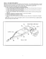
Identify the “road side” and “curb side” of your trailer per the picture below.  The mounting brackets have an access 
hole in them so the wire harness can be attached to the light.  On the wire harness the yellow/brown wire is for the 
road side light and the green/brown wire is for the curb side light.  The white wire is a ground wire. 
To attach the wire harness to the lights and frame proceed as follows. 

1.  Strip ½” off the ends of the yellow/brown and green/brown wires. 
2.  On the road side light put the yellow wire through the access hole and into the top left hole on the back of 

the light.  Push the brown wire into the top right hole. 

3.  On the curb side light put the green wire through the access hole and into the top left hole on the back of 

the light.  Push the brown wire into the top right hole. 

4.  Once the wires are attached in their correct holes attach the wire harness to the frame with the provided 

cable ties. 

5.  Attach the curb side wire to the frame at points 1, 2 and 3 per the drawing. 
6.  Attach the road side wire to the frame at point 4. 
7.  Attach both wires together at points 5, 6, 7 and 8. 
8.  Strip 1” from the end of the ground wire and wrap it around one of the bolts on the trailer hitch.  Retighten 

this bolt. 

NOTE:  Once the wires are being secured together (point 5), it is recommended that they be wrapped together 
with electrical tape every twelve inches. 


Summary of Contents for 18.0 HP

Page 1: ...CHP This manual contains information concerning proper and improper operating procedures warnings maintenance troubleshooting assembly and tips Everyone who operates this machine should read these ins...

Page 2: ...2...

Page 3: ...ED USE Never use your chipper for any other purpose than chipping limbs It is designed for this use and any other use many cause serious injury DANGER Rotating cutting blade Keep hands and feet out of...

Page 4: ...obstacles which could cause you to stumble or fall Never place your hands feet or any part of your body in the chipper chute discharge or near any moving part while the engine is running Keep clear o...

Page 5: ...oving parts have stopped Disconnect both spark plug wires and keep them away from the spark plugs to prevent accidental starting Do not use flammable solutions to clean air filter Check the blade and...

Page 6: ...s unit is equipped with an internal combustion engine and should not be used on or near any unimproved forest covered brush covered or grass covered land unless the engine s exhaust system is equipped...

Page 7: ...10 EA CABLE TIES 2 EA HITCH ARM MOUNTING PLATES 1 EA ENGINE KEY TOOLS REQUIRED FOR ASSEMBLY 7 16 Wrench or Socket 2 required 1 2 Wrench or Socket 2 required 3 4 Wrench or Socket 2 required STEP I UNP...

Page 8: ...the back of the light Push the brown wire into the top right hole 3 On the curb side light put the green wire through the access hole and into the top left hole on the back of the light Push the brow...

Page 9: ...r leaded premium grades of gasoline are acceptable substitutes Do not mix oil with gasoline Do not use gasoline left over from last season or that has been stored for more than 30 days TO ADD OIL The...

Page 10: ...runs smoothly and then to NO CHOKE POSITION by pushing choke ring in NOTE If engine fires but does not continue to run move choke lever to NO CHOKE POSITION and crank engine until it starts NOTE If e...

Page 11: ...UTCH To free a jammed flywheel stop the engine remove both spark plug wires and remove the material left in the chipping chamber It may be necessary to remove the deflector cover item 1 pg 17 to allow...

Page 12: ...ill find information included referring to operation and maintenance of the chipper engine Look it over carefully BE CERTAIN TO SERVICE THE ENGINE BEFORE YOU START IT 4 When the steel chipping knives...

Page 13: ...O SHARPEN KNIVES FREE HAND Knives must be parallel ground and kept in a matched set Take the knives to a sharpening service to be sharpened After sharpening the knives be sure to re gap the knives and...

Page 14: ...urn Clutch is slipping or flywheel is jammed or stopped A Immediately stop engine B Remove spark plug wire C Turn flywheel by hand to be sure it turns freely D Check belt tension Chipping action seems...

Page 15: ...if needed Anti seize compound Good grade multi purpose lithium grease 40 HOURS Change engine oil 2 Check tire pressure Remove and sharpen or replace chipper knives Per manufacturer s specifications Ad...

Page 16: ...er shoes are changed replace all springs DISASSEMBLY OF EXISTING CLUTCH 1 Remove retainer ring and press off drum assembly 2 Release one hook end of spring from shoe pin Use tape wrapped pliers to avo...

Page 17: ...11 0248 BELT GUARD WELDMENT 28 1 030 0232 GAS TANK 29 1 913 0053 GAS TANK MOUNTING BRACKET 30 1 913 0054 ENGINE BELT TIGHTENER 31 1 030 0239 HOSE AND CLAMP ASSEMBLY 33 1 913 0203 BATTERY SPACER 34 1 0...

Page 18: ...18 PARTS BREAKDOWN C182 CHP CHIPPER...

Page 19: ...E 11 3 090 0257 20 X 1 SOCKET FLAT HEAD SCREW 12 1 911 0055 WEAR PLATE 13 10 090 0460 5 16 18 NYLOCK NUT 14 8 090 0233 5 16 USS FLATWASHER 15 1 911 0164 CHIPPER HOPPER 16 4 090 0462 5 16 18 X CARRIAGE...

Page 20: ...20 PARTS BREAKDOWN 913 0215 CHIPPER BASIC MACHINE...

Page 21: ...IS RUNNING 2 READ INSTRUCTIONS THOROUGHLY BEFORE OPERATING THE MACHINE 3 NEVER OPERATE THE CHIPPER WITHOUT THE FEED CHUTE SECURELY IN PLACE 4 USE GLOVES AND APPROVED SAFETY GLASSES WHEN OPERATING 5 DO...

Page 22: ...22 COUNTRY HOME PRODUCTS Meigs Road P O Box 25 Vergennes Vermont 05491 1 800 DR OWNER 376 9637 2000 CHP Inc 157611 09 18 01...

Reviews: