10
D R
®
HORIZONTAL/VERTICAL LOG SPLITTER
1.
Remove the plastic shipping caps from the Wheels. Make sure the bearing
remains seated when removing the cap. If the bearing comes out with the
cap, reinsert it into the hub.
2.
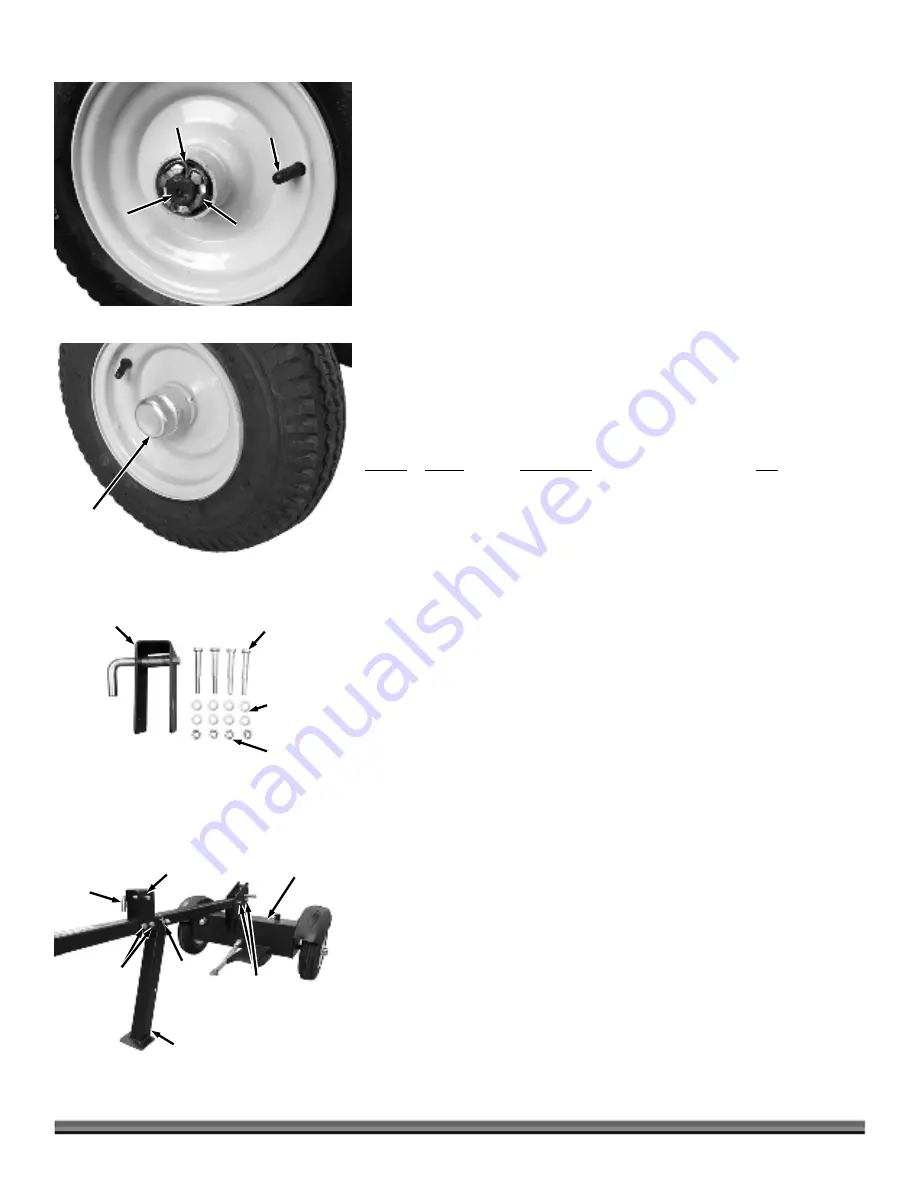
Block the reservoir assembly up off the ground and position a wheel onto the
axle (valve stem facing out) (
Figure 6
).
3.
Screw the Castle Nut onto the Axle and tighten it with an Adjustable Wrench
to seat the Bearing.
4.
Back the Castle Nut off and then snug it up to the Bearing lightly.
5.
Insert a Cotter Pin through the slots of the Castle Nut and into the hole in
the Axle.
6.
Bend the ends of the cotter pin with Needle Nose Pliers so they are tight
against the Castle Nut.
7.
Tap the Dust Cap onto the wheel using a Soft Faced Hammer (
Figure 7
).
8.
Repeat these steps for the other Wheel.
Installing the Tow Bar
Parts Supplied in Hardware Kit #3 (
Figure 8
):
Item # Part
# Description
Qty
1 ............. 33712 .............. Horizontal Beam Lock .......................... 1
2 ............. 33705 .............. Bolt, Hex, M10 X 80 .............................. 4
3 ............. 30250 .............. Washer, Flat, M10 ................................. 8
4 ............. 30249 .............. Nut, Nylon Lock, M10 ........................... 4
Compare the contents of the Hardware Kit #3 with the “Parts Supplied” list
above. If you have any questions please contact us at www.DRpower.com or call
1-800-DR-OWNER (376-9637) for assistance.
Note:
When installing the Bolts, Washers, and Locknuts, install the Washers so that
one Washer is against the head of the Bolt, and the other Washer is against the
Locknut.
1.
Remove the Pin and Hitch Clip that locks the Jack Stand in place (
Figure 9
).
Rotate the Jack Stand down and secure it with the Pin and Hitch Clip.
2.
Secure the Rear of the Tow Bar to the Reservoir Assembly using two M10 x
80 Bolts, four Flat Washers, and two Locknuts. Tighten the Hardware using a
16mm Wrench for the Bolt and a 17mm Wrench for the Locknut.
Note:
In the next step, the Horizontal Beam Lock must be installed with the handle
on the RIGHT SIDE as shown in
Figure 9.
The slot in the beam bracket will only
latch properly to the handle if it is installed as shown.
3.
Install the Horizontal Beam Lock onto the Tow Bar as shown using two M10
x 80 Bolts, four Flat Washers, and two Locknuts. Tighten the Hardware using
a 16mm Wrench for the Bolt and a 17mm Wrench for the Locknut.
1
2
3
4
Figure 8
Dust Cap
Figure 7
Figure 6
Castle
Nut
Cotter Pin
Axle
Valve
Stem
Figure 9
Horizontal
Beam Lock
Handle
this
Side
Bolts, Flat
Washers and
Locknuts
Reservoir
Assembly
Bolts, Flat
Washers and
Locknuts
Jack Stand
Pin and
Hitch
Clip


