CONTACT US AT
w w w .D Rpow e r .com
11
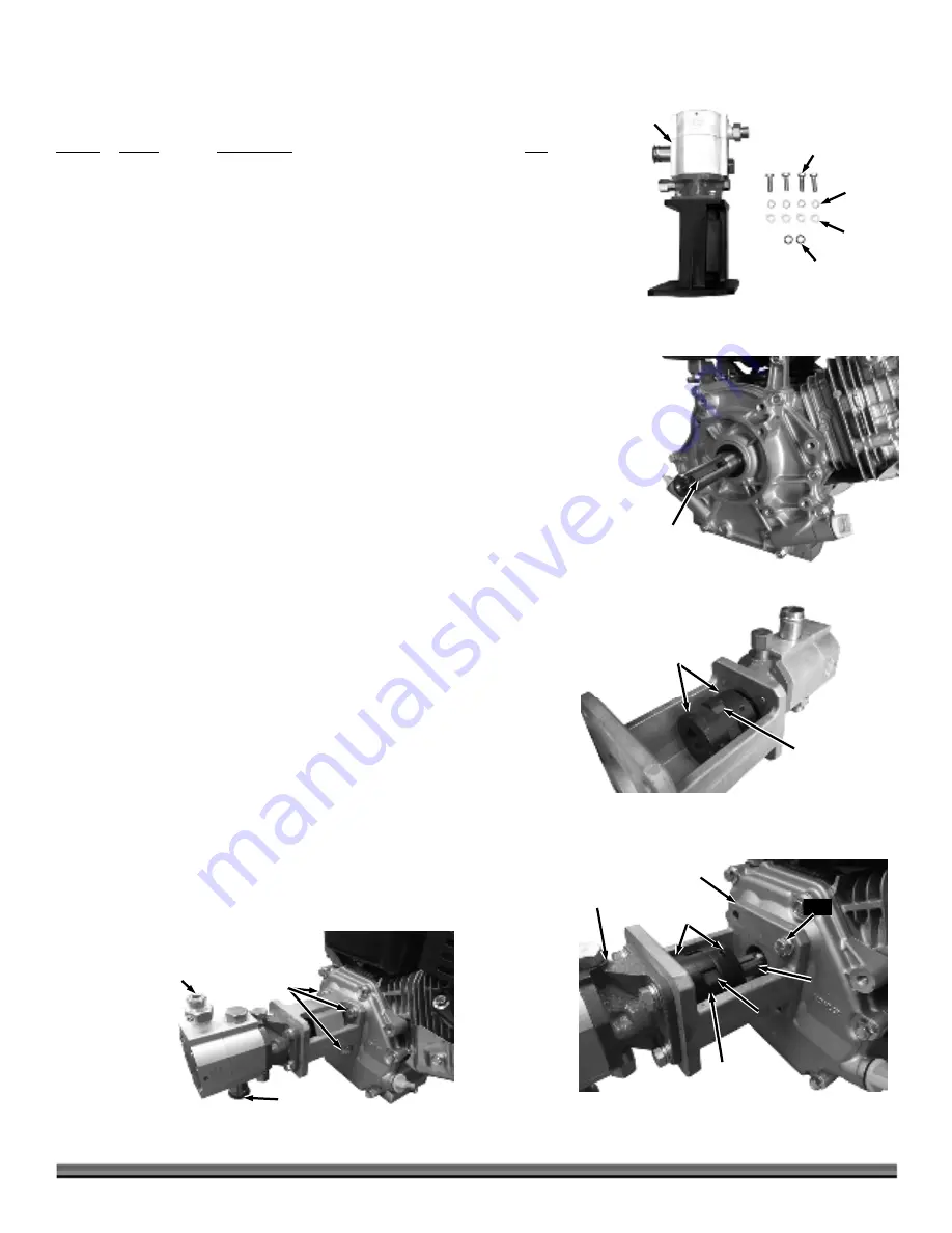
Installing the Pump Assembly
Parts Supplied in Hardware Kit #4 (
Figure 10
):
Item # Part
# Description
Qty
1 ............. 33739 .............. Two Stage Pump Assembly (22 and 28 Ton) ....... 1
33740 .............. Two Stage Pump Assembly (34 Ton) ................... 1
2 ............. 13286 .............. Bolt, Hex, 5/16-24 ................................................. 4
3 ............. 30247 .............. Washer, Lock, M8 .................................................. 4
4 ............. 11243 .............. Washer, Flat, M8 ................................................... 4
5 ............. 35476 .............. O-Ring, 11mm X 2mm .......................................... 2
Compare the contents of the Hardware Kit #4 with the “Parts Supplied” list
above. If you have any questions please contact us at www.DRpower.com or call
1-800-DR-OWNER (376-9637) for assistance.
Note:
The O-Rings (Item 5) in Hardware Kit #4 are to be used in the “Installing the
Hydraulic Hoses” section in this Chapter. Set the O-Rings aside in a secure
place until you reach this step.
1.
Remove the Engine from its box and place it on a level service.
2.
Slowly pull on the engine starter cord to position the key slot at the top of the
shaft (
Figure 11
).
3.
Using a soft face hammer, gently tap the Key (located in the Engine Box) into
the Key Slot on the Engine Shaft.
4.
The Coupling may have separated during shipping. Ensure that the two
Coupling Halves are together with the Nylon Insert in the center (
Figure 12
).
5.
Position the Pump Assembly, with the opening facing up, onto the Engine
Shaft so that the key slides into the Coupling (
Figure 13
). Push the Pump
Assembly onto the shaft until the Pump Mount is flush with the Engine.
Temporarily install a 5/16-24 Bolt to hold the Pump against the Engine.
6.
Use a 3mm Allen Wrench to remove one of the Set Screws on the Coupling.
Apply thread lock to the Set Screw and reinstall it. Tighten the Set Screw to
secure the Coupling. Repeat this step for the other Set Screw.
Note:
If the Threaded Fitting on the Pump is already on top as shown in
Figure 14
,
skip step 7 and continue to step 8.
7.
Remove the Bolt installed in Step 5. Rotate the Pump Assembly so that the
Threaded Fitting is on the top of the Pump (
Figure 14
).
8.
Secure the Pump Assembly using four 5/16-24 Bolts, M8 Lock Washers,
and M8 Flat Washers. Tighten the Hardware using a 1/2” Wrench.
9.
Remove the plastic Shipping Cap From the bottom of the Pump.
Bolts, Lock
Washers, and
Flat Washers
Figure 14
Shipping
Cap
Threaded
Fitting
Figure 13
Coupling
Pump
Assembly
Set Screws
Engine
Shaft
Pump Mount
Nylon
Insert
Bolt
Coupling
Nylon
Insert
Figure 12
Figure 11
Key
1
2
3
4
Figure 10
5


