26
D R
®
HORIZONTAL/VERTICAL LOG SPLITTER
4. Refill the Hydraulic Tank.
Note:
Refer to
Figure 30
in the “Adding Hydraulic Fluid” section in Chapter 2 for
recommended Hydraulic Fluid Types.
a.
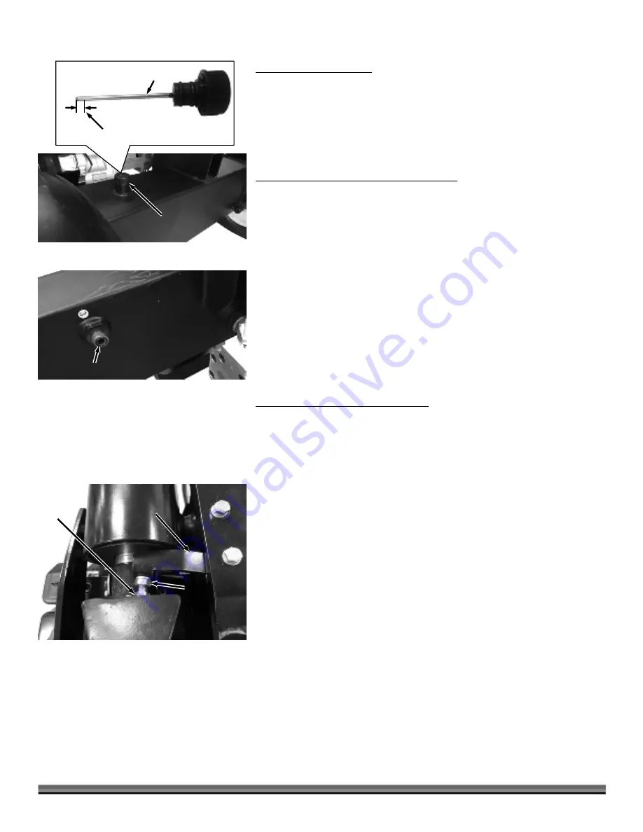
Remove the Reservoir Dipstick and fill the tank with the
recommended hydraulic fluid until it reaches the Initial Fill Line on
the Dipstick
(Figure 61)
.
b.
Replace the Dipstick when the fluid has reached the proper level.
5. Drain and refill the piston end of the cylinder.
a.
Position the Oil Return Hose into the Waste Fluid Container.
b.
Hold the control handle in the reverse position and pull the engine
pull start cord until the rod is fully retracted to drain the piston end
of the cylinder.
c.
Inspect the O-Ring
(11mm X 2mm)
on the Oil Reservoir for
damage
(Figure 62).
If the O-Ring is damaged or missing, replace it.
d.
Reconnect the Oil Return Hose to the Oil Reservoir.
e.
Extend the cylinder by holding the control valve handle forward and
pulling on the engine’s pull start cord until the cylinder is completely
extended. This step refills the piston end of the cylinder.
f.
Recheck the Fluid Level to ensure it is about 1/4" above the bottom
of the dipstick. Add fluid if needed. Do not overfill.
Note:
Do not refill to the Initial Fill line. This mark is only to be used in step 4. The
proper level for operation is when the fluid is about 1/4" above the bottom of the
dipstick.
6. Start the engine and cycle the cylinder.
a.
Replace the spark plug and spark plug wire.
b.
Start the engine and cycle the cylinder several times.
c.
Retract the cylinder and shut off the engine.
d.
Recheck the Fluid Level to ensure it is about 1/4" above the bottom
of the dipstick. Add fluid if needed. Do not overfill.
Adjusting the Handle Return Lever
A Handle Return Lever is attached to the Valve Bracket to manually stop the
Wedge when it is fully retracted. The Lever may need to be adjusted if:
- The Wedge is not retracting fully.
- The Engine stalls and the Actuator Handle stays in the retract position with the
Wedge is fully retracted.
Tools Needed:
13mm Wrench
14mm Wrench
1.
Loosen the Jam Nut using a 14mm Wrench (
Figure 63
).
2.
Adjust the Bolt using a 13mm Wrench.
Screw Bolt into the Return Lever if the Operator lever is being pushed
forward before fully retracting.
Unscrew the Bolt from the Return Lever if the Operator lever is not
being disengaged and the Engine is stalling.
3.
When finished, hold the Bolt with the 13mm Wrench as you tighten the Jam
Nut against the Lever using a 14mm Wrench. Test and readjust as needed.
Jam
Nut
Figure 63
Adjusting
Bolt
Handle
Return
Lever
Valve
Bracket
Oil
Reservoir
O-Ring
Figure 62
Figure 61
Reservoir
Dipstick
Initial Fill Line
1/4"
Operating Level


