background image

contact us at 

www.DRpower.com

          19


TILLING 

Tilling is digging in, turning over and breaking up garden soil and prepare a seedbed for planting. Best tilling depth is 4” 
(100mm) to 6” (150mm). A tiller will also clear the soil of unwanted vegetation. The decomposition of this vegetation matter 
enriches the soil. 

Avoid tilling soil that is too dry as it will pulverize and produce a dust that will not hold water. Water a few days before tilling. Also, 
tilling soil that is too wet will produce unsatisfactory clods. Wait a day or two after heavy rain for the soil to dry. 

Better growth will be obtained if an area is tilled properly and used soon after tilling to preserve the moisture content.. 

The type of soil and working conditions will determine the actual setting of the tilling depth. In some soils, the desired depth is 
reached first pass over garden. In other soils, the desired depth is obtained by going over the garden two or three times. In later 
case, the depth regulator rod should be lowered before each succeeding pass over the garden. Passes should be made across the 
length and width of the garden alternately. Do not try to dig too deeply in the first pass. If the machine jumps or bucks, allow    the 
unit to move forward at a slightly faster rate. 

If the tiller stops forward motion and tries to dig in one spot, rock the handles from side to side to start it moving forward again. 

Rocks which are turned up should be removed from the garden area. 


Move the depth stake pin lever to the unlock position (See Figure 8a, Illustration 2). Hold the depth stake limiter to pull the 
depth stake up for increasing tilling depth. Place depth stake pin in the hole of the depth stake to lock in position at desired 
depth. 


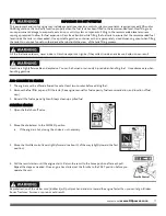
Place shift lever indicator in counter rotating ( 

 ) till position when tilling hard soil. 


Hold the drive control bar against the handle to start tilling movement. Tines and wheels will both turn. 


Move throttle control to “FAST” position for deep tilling. To cultivate, throttle control can be set at any desired speed, 
depending on how fast or slow you wish to cultivate. 

TURNING 


Release the drive control bar. 


Move throttle control to “SLOW” position. 


Place shift lever indicator in “F” (forward) position. Tines will not turn. 


Lift handle to raise tines out of ground. 


Swing the handle in the opposite direction you wish to turn, being careful to keep feet and legs away from tines. 


When you have completed your turn-around, release the drive control bar and lower handle. Place shift lever in (till) position 
and move throttle control to desired speed. To begin tilling, hold drive control bar against the handle. 

CULTIVATING 

Cultivating is loosening or digging around growing plants to disrupt weeds and aerate soil. Less than 2” (50mm) depth is 
always desirable. 


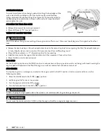
Place  shift  lever  indicator  in  forward rotating ( 

 ) till position when cultivating soft ground or tilling pre-tilled soil. 


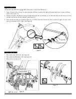
Move both the depth stake pin lever and  the  drag  stake pin lever to the unlock position (See Figure 8a, Illustration 2 & Figure 
11). Hold the depth stake limiter to pull the depth stake up for increasing tilling depth. Place depth stake pin in the hole of the 
depth stake to lock in position at desired depth. Lower drag stake to the “Lowered position” (See Figure 11) and lock it in 
position. 


Hold the drive control bar against the handle to start cultivating movement. Tines and wheels will both turn. 


Move the throttle control to the fast position for deep cultivating. To cultivate, throttle control can be set at any desired speed, 
depending on how fast or slow you wish to cultivate. 


Always lower the drag stake when using the forward rotating tine drive. 

IMPORTANT: Always release drive control bar before moving shift lever into another position.


Summary of Contents for PRO XL-DRT

Page 1: ...nstructions before operating the DR PRO XL DRT DR PRO XL DRT Dual Rotating Tine Rototiller SAFETY OPERATING INSTRUCTIONS Serial No Order No DR Power Equipment Toll free phone 1 800 DR OWNER 376 9637 F...

Page 2: ...2 DR PRO XL DRT...

Page 3: ...ence and ready reference enter the Serial Number and Order Number in the space provided on the front cover of this manual Additional Information and Potential Changes DR Power Equipment reserves the r...

Page 4: ...components can only be adjusted by an authorized engine manufacturer s service center Labels Your DR PRO XL DRT carries prominent labels as reminders for its proper and safe use Shown below are copie...

Page 5: ...individuals who are familiar with these rules of safe operation to use your machine Never place your hands feet or any part of your body near or under any moving part while the machine is running To b...

Page 6: ...mper with safety devices Check their proper operation regularly Do not change the engine governor settings or modify the engine speed Modifications will void your warranty To reduce fire hazard keep t...

Page 7: ...chine is to till soil Do not use it for any other purpose Give complete and undivided attention to the job at hand Before you use your new machine be sure you know how to disengage the tines and stop...

Page 8: ...as large stones roots or stumps If the unit strikes a foreign object stop the engine disconnect the spark plug thoroughly inspect the machine for any damage and repair the damage before restarting and...

Page 9: ...aintain this equipment in compliance with state regulations is a misdemeanor under California law and may be in violation of other state and or federal regulations Contact your State Park Association...

Page 10: ...beginning these procedures If you have any questions at all please feel free to contact us at www DRpower com DR PRO XL DRT Controls and Features Figure 2 Throttle Control Drive Control Bar Shift Lev...

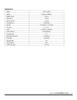
Page 11: ...cement 208 cc Start Type Recoil Fuel Tank Size 75 gal Transmission Chain Gear Speeds 1 Forward 1 Reverse Tire Size 13 5 Tines 10 Tiller 2 Hammer Tine Direction Dual Rotation TineDiameter 13 Depth Adju...

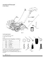
Page 12: ...2 3 41523 Flat Washer 8 1 4 41552 Bolt M8x25 1 5 41564 Lever Knob 1 6 41583 Rubber Cap 1 7 33332 Limiter Pin 1 8 33332 Spring Washer 5 1 Compare the contents of the shipping crate with Figure 3 and F...

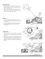
Page 13: ...gure 6 Illustration 1 2 Insert the upper end of shift rod into hole of shift lever Fasten with bridge clip and washer see Figure 6 Illustration 2 Throttle Control 1 The M6 50 screw and nut have been f...

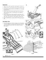
Page 14: ...e M8 25 bolt washer and plastic screw head into the first hole of depth stake Hold the plastic screw head in place with pliers while screwing the bolt in see Figure 8a Illustration 5 6 Adjust the dept...

Page 15: ...ontrol bar and tiller will move forward REVERSE R Move the shift lever indicator to R position Engage the drive control bar and tiller will move backward NEUTRAL N Release the control bar to stop move...

Page 16: ...ve the oil fill cap dipstick to add oil 3 Using a funnel add oil up to the FULL mark on the dipstick See engine manual for oil capacity oil recommendation and location of fill cap The engine is shippe...

Page 17: ...ured when handling fuel Use extreme care when handling gasoline Fill the fuel tank outdoors never indoors Gasoline vapors can ignite if they collect inside an enclosure Explosion can result This equip...

Page 18: ...ion Hold drive control bar against the handle and tiller will move backward If you find the shift lever difficult to move or find it hard to shift gears tryoneofthefollowing Briefly engage the drive c...

Page 19: ...tilling hard soil Hold the drive control bar against the handle to start tilling movement Tines and wheels will both turn Move throttle control to FAST position for deep tilling To cultivate throttle...

Page 20: ...against the handle to start tiller movement Tines will not turn Move throttle control to desired speed IDLE SPEED Set the throttle control lever to the SLOW position to reduce stress on the engine whe...

Page 21: ...ssed air to remove all contaminants from the machine Then use high quality light oil to lubricate all moving parts 5 Replace the spark plug wire GEARBOX The gearbox was filled with lubricant to the pr...

Page 22: ...kwise or counter clockwise with a 6mm wrench until you have reached your desired tightness see Figure 13 3 Once you have reached your desired cable tension hold the adjustment barrel with a 6mm wrench...

Page 23: ...ide the belt roller off its stud below the large transmission pulley See Figure 17 illustration 3 4 Remove the belt from the engine and idler pulley Rotate the transmission pulley and pull the belt ge...

Page 24: ...ine damage 3 While the engine is still warm drain the oil from the engine Refill with fresh oil of the grade recommended in the Engine Manual 4 Use clean cloth to clean off the outside of the machine...

Page 25: ...n blocked fuel line or stale fuel Vent plugged Water or dirt in fuel system Dirty air cleaner Improper carburetor adjustment Connect and tighten spark plug wire Move choke lever to OPEN position Clean...

Page 26: ...regulator rod Set the throttle lever at lower speed Tines do not engage Foreign object lodged in tines Tine clevis pin s missing Belt worn and or stretched Pulley and idler not in correct adjustment...

Page 27: ...contact us at www DRpower com 27...

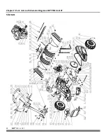
Page 28: ...28 DR PRO XL DRT Chapter 7 Parts Lists and Schematic Diagrams DR PRO XL DRT Schematic...

Page 29: ...06 41566 Throttle Cable 107 41567 Throttle Lever Assy 108 41568 Screw M6x50 109 41569 Lock Nut M6 110 41570 Tensioner Pulley Cable 111 41571 Pulley Cable Drag Rod Ref Part Description 113 41573 End Ca...

Page 30: ...lver 4in 41513 Label Main Branding 1 41514 Label Branded Info 41515 Label Warning 1 41546 Label Warning 2 41517 Label Branding 2 41518 Label Drive 41519 Label Gear Tine 41520 Label Throttle 41521 Labe...

Page 31: ...fined by the manufacturer s owner s manuals The warranty holder is responsible for replacement of normally wearing parts such as the Drive Belt Tines Depth Stake Shear Pins Spark Plug and Air Filter A...

Page 32: ...30W If your DR PRO XL DRT will be idle for more than 30 days we recommend using a gas stabilizer or draining the fuel system This will prevent sediment from gumming up the carburetor If there is dirt...

Reviews: