34
DR
®
ROTO-HOG™ POWER TILLER
Removing and Replacing the V-Belt
Replace the Tine Drive V-Belt if damaged from slipping under heavy loads or if it shows cracks or frayed
edges.
WHEN PERFORMING ANY MAINTENANCE, YOU MUST FIRST SHUT OFF THE ENGINE, WAIT FIVE (5)
MINUTES TO ALLOW PARTS TO COOL AND DISCONNECT THE SPARK PLUG WIRE, KEEPING IT AWAY
FROM THE SPARK PLUG.
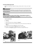
DO NOT MOVE OR REMOVE THE BELT GUIDE (
FIGURE 20
). IF YOU ACCIDENTALLY ALTER THE
POSITION OF THE BELT GUIDE, RETURN IT TO THE CORRECT SETTING OF 6-1/4" VERTICAL INCHES
FROM THE FENDER TO THE BOTTOM OF GUIDE (
FIGURE 20
).
Tools and Supplies Needed:
•
Screwdriver
•
7/16" Socket
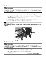
1. Remove the Screw from the top of the Belt Guard (
Figure 19
).
2. Remove the Hex Nut from the rear of the Belt Guard using a 7/16" Socket and remove the Belt Guard
(
Figure 19
).
3. Disengage the Tine Clutch Lever (
Figure 19
) and remove the worn Belt.
Tip:
Lifting up on the Clutch Idler Pulley (
Figure 20
) may help in removing the Belt.
4. Reinstall a new Belt (
Figure 20
), engage the Tine Clutch Lever, and replace the Belt Guard.
Figure 19
Figure 20
Disengage
Belt Cover
Top Screw
Hex Nut
Clutch Idler Pulley
Belt Routing
Belt Guide
Fender
6-1/4"
Summary of Contents for ROTO-HOG
Page 14: ...10 DR ROTO HOG POWER TILLER ...
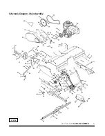
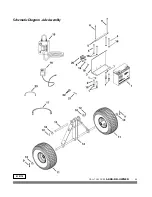
Page 45: ...CALL TOLL FREE 1 800 DR OWNER 41 Schematic Diagram Main Assembly 070718 ...
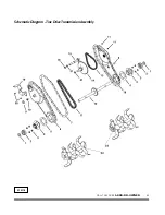
Page 47: ...CALL TOLL FREE 1 800 DR OWNER 43 Schematic Diagram Tine Drive Transmission Assembly 070718 ...
Page 49: ...CALL TOLL FREE 1 800 DR OWNER 45 Schematic Diagram Axle Assembly 070718 ...
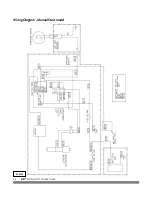
Page 50: ...46 DR ROTO HOG POWER TILLER Wiring Diagram Manual Start model 070725 ...
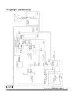
Page 51: ...CALL TOLL FREE 1 800 DR OWNER 47 Wiring Diagram Electric Start model 070725 ...


