7
Draganflyer V Ti Assembly
continued
3)
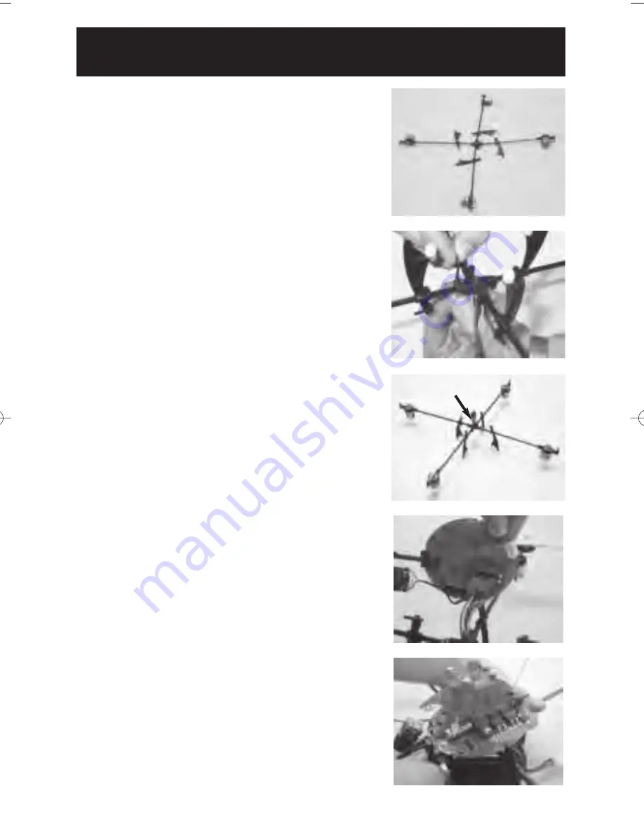
Lay out the frame. The front motor arm will
already be inserted into the cross section. The front
vertical riser will also have a colored dot on it. Do
not remove this until after assembly.
See photo
7-A
4)
Insert the remaining 3 frame arms into the cross
section, ensuring that all frame arms are securely
pushed into the cross section. Note: It may be nec-
essary to pull the wires at the cross section to take
up any slack as the frame arms are inserted into
place.
See photo
7-A
5)
Screw four 2-56 x 3/8” hex socket cap bolts into
the cross section, attach nuts and tighten frame
arms in place using the supplied 5/64” Allen key
wrench. Note: Do not over-tighten as you will dis-
tort the plastic pieces. The nuts recess into the larg-
er opening of the hole.
See photo
7-B
6)
Tighten motor mounts using 2-56 x 3/8” allen bolts
and nuts. Ensure that the motors are straight up and
down and pushed all the way into the mount.
See
photo
7-C
7)
Hold the circuit board over the cross section and
insert the main wire harness plug into the large
connector on the circuit board.
Orient the circuit
board’s LED eyeballs towards the front motor.
The front is marked by the red dot on the vertical
riser. If you are still unsure as to which motor is
the front, it has one red and one black wire
attached to it. Note: Be sure the opening of the
center area of the cross section is facing upward
with the harness protruding straight up.
See photo
7-D
8)
Slide the vertical risers towards the circuit board
until they capture the edge of the circuit board at
the notches on the circuit board and tighten the
vertical riser using (4) 2-56 x 3/8” Hex Socket
bolts and nuts.
See photo
7-E
7-A
7-B
7-E
7-D
7-C
Main Wire Harness
pointing upwards
DF5_manual_Imposed_Jan4_05 1/7/05 10:38 AM Page 15
Summary of Contents for DraganFlyer V Ti
Page 1: ...INVENTING THE FUTURE OF RADIO CONTROLLED FLIGHT...
Page 21: ...20...


