background image

3

Setup and Installation

3-12

Narkomed GS Setup and Installation Manual

Draeger Medical, Inc.

Installing the 

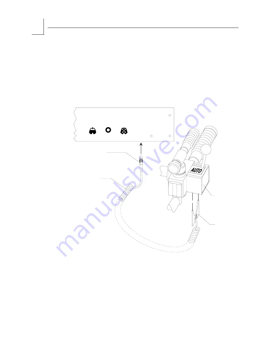
AUTO/BAG 

Sensor Cord

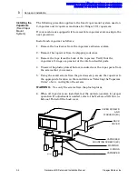
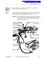
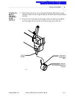
1. Push the manual/automatic selector sensor into the underside of the 

manual/automatic selector valve housing until it snaps into place. Note 
that the sensor is keyed and only fits into the housing one way.

2. Align the key on the sensor cord connector with the keyway on the 

AUTO/BAG SELECTOR interface underneath the ventilator box. Then 
push the connector in until it snaps into place.

SU00602

INTERFACE
CABLE

SENSOR CORD
CONNECTOR

MANUAL/

AUTOMATIC

SELECTOR

VALVE

REAR PANEL OF

VENTILATOR BOX

2

VOLUME

SENSOR

OXYGEN

SENSOR

BREATHING

PRESSURE

AUTO/BAG

SELECTOR

MANUAL/

AUTOMATIC

SELECTOR

SENSOR

RETURN TO CD-ROM TABLE OF CONTENTS

RETURN TO THIS MANUAL'S TABLE OF CONTENTS

Summary of Contents for Narkomed GS

Page 1: ...5 February 2004 2004 Draeger Medical Inc Part Number 4113852 006 Rev J Installation Manual Setup and Narkomed GS Anesthesia System RETURN TO CD ROM TABLE OF CONTENTS RETURN TO THIS MANUAL S TABLE OF CONTENTS ...

Page 2: ...RETURN TO CD ROM TABLE OF CONTENTS RETURN TO THIS MANUAL S TABLE OF CONTENTS ...

Page 3: ...g the Absorber System 3 7 Installing the Breathing Pressure Pilot Line 3 10 Installing the Auto Bag Sensor Cord 3 12 Installing the Oxygen Sensor 3 13 Installing the Ultrasonic Flow Sensor 3 14 Installing the Bain Circuit Adapter 3 15 Installing the Fresh Gas Oxygen Sensor 3 18 Connecting the Open Reservoir Scavenger System 3 19 Connecting the Scavenger Interface for Passive Systems 3 20 Installin...

Page 4: ... 5 Calibrations 6 14 6 6 Absorber Maintenance 6 14 6 7 High Pressure Leak 6 16 6 8 Breathing System 6 16 6 9 Oxygen Analyzer 6 20 6 10 Flowmeters Concentrations 6 21 6 11 High Pressure Regulator 6 23 6 12 Low O2 Supply 6 25 6 13 Oxygen Supply Failure Protection 6 26 6 14 Pressure Monitor 6 26 6 15 Ventilator 6 27 6 16 Bellows Adult 6 28 6 17 Bellows Pediatric External 6 29 6 18 Bellows Pediatric I...

Page 5: ...ical Inc Narkomed GS Setup and Installation Manual 1 Introduction Section contents Introduction 1 2 Warnings 1 2 Cautions 1 2 Notes 1 2 RETURN TO CD ROM TABLE OF CONTENTS RETURN TO THIS MANUAL S TABLE OF CONTENTS ...

Page 6: ...trical power and verifying correct power up Test Procedure Section 6 contains instructions for testing the machine using the Periodic Manufacturer s Certification PMC procedure The machine must be tested following setup and installation The test procedure must be performed by or under the direct supervision of an authorized representative of DrägerService NOTE The PMC procedure must also be perfor...

Page 7: ...Narkomed GS Setup and Installation Manual 2 Moving the Narkomed GS Section contents Getting the Machine Ready to Move 2 2 Moving the Machine 2 2 RETURN TO CD ROM TABLE OF CONTENTS RETURN TO THIS MANUAL S TABLE OF CONTENTS ...

Page 8: ...ds that two people move the anesthesia machine to aid in maneuverability Exercise special care so that the machine does not tip when moving up or down inclines around corners and across thresholds for example in door frames and elevators Do not attempt to pull the machine over any hoses cords or other obstacles on the floor 1 Unlock the front casters by stepping on their locking levers Do not atte...

Page 9: ...rkomed GS 2 Draeger Medical Inc Narkomed GS Setup and Installation Manual 2 3 PUSH PULL BAR OPTIONAL HANDLE SU87026 CASTER LOCKING LEVERS RETURN TO CD ROM TABLE OF CONTENTS RETURN TO THIS MANUAL S TABLE OF CONTENTS ...

Page 10: ...RETURN TO CD ROM TABLE OF CONTENTS RETURN TO THIS MANUAL S TABLE OF CONTENTS ...

Page 11: ...ne 3 10 Installing the Auto Bag Sensor Cord 3 12 Installing the Oxygen Sensor 3 13 Installing the Ultrasonic Flow Sensor 3 14 Installing the Bain Circuit Adapter 3 15 Installing the Fresh Gas Oxygen Sensor 3 18 Connecting the Open Reservoir Scavenger System 3 19 Connecting the Scavenger Interface for Passive Systems 3 20 Installing the Patient Line Boom Arm 3 22 Installing the Manual Sphygmomanome...

Page 12: ...6 Install the oxygen sensor 7 Install the ultrasonic flow sensor 8 Install the Bain Circuit adapter optional 9 Install the fresh gas oxygen sensor adapter optional 10 Connect the open reservoir scavenger system optional 11 Connect the passive scavenger system optional 12 Install the patient line boom arm optional 13 Install the manual sphygmomanometer gauge optional 14 Install the second shelf opt...

Page 13: ...3 Hammer the pin into the hole until it is flush with the swivel arm Selecting the Vaporizer Order Fixed Vapor Mount System You must install the vaporizers in the following order as viewed from the front of the machine unless otherwise specified by the customer Left position Halothane Center position Enflurane Right position Isoflurane or desflurane NOTE To install a TEC 6 desflurane vaporizer see...

Page 14: ...er Verify that the vaporizer s O rings are present at the inlet and outlet ports 4 Unscrew the plastic plates that are mounted over the vapor ports Save the screws that you remove 5 Using the saved screws from the previous step secure the vaporizer to the appropriate location on the manifold see Selecting the Vaporizer Order above and tighten the screws WARNING Use only the screws from the plastic...

Page 15: ... ports on the vaporizer manifold and verify that each port has an O ring 2 Move the selector lever to the right 3 Place the vaporizer down over the left manifold ports and turn its locking lever 90 clockwise to secure the vaporizer to the manifold 4 Move the selector lever to the left 5 Place the second vaporizer down over the right manifold ports and turn its locking lever 90 clockwise to secure ...

Page 16: ...up and Installation Manual Draeger Medical Inc SU00114 SELECTOR LEVER LOCKING LEVER REMOVABLE VAPORIZER MOUNTING ARRANGEMENT TOP VIEW O RINGS VAPORIZER MOUNTING MANIFOLD RETURN TO CD ROM TABLE OF CONTENTS RETURN TO THIS MANUAL S TABLE OF CONTENTS ...

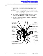
Page 17: ...y with current ANSI standards 1 Place the absorber mounting stud into the top of the absorber pole 2 Tighten the set screw on the absorber pole to lock the absorber in place WARNING Do not pinch or kink the fresh gas hose leading from the fresh gas common outlet to the absorber 3 Pull out the fresh gas locking bar located on the front of the Narkomed GS to its extended position Insert the 15 mm ma...

Page 18: ...trasonic flow sensor 7 Attach the breathing bag to the swivel bag mount 22 mm terminal marked BREATHING BAG 22MM BREATHING HOSES P N 9995132 INSPIRATORY VALVE W 22MM BREATHING HOSE TERMINAL ABSORBER Y PIECE ABSORBER MOUNTING STUD SWIVEL BAG MOUNT W 22MM BREATHING BAG TERMINAL 19MM SCAVENGER HOSE P N 9995230 APL VALVE W 19MM SCAVENGER HOSE TERMINAL FRESHGAS LOCKING DEVICE W 15MM FEMALE FITTING FRES...

Page 19: ...stically altered compliance characteristics and altered conductivity in the case of conductive bags 8 Connect the 19 mm scavenger hose between the 19 mm terminal marked SCAVENGER HOSE on the rear of the APL valve and the 19 mm terminal marked SCAVENGER HOSE on the scavenger ULTRASONIC FLOW SENSOR OXYGEN SENSOR SU98101B VENTILATOR BELLOWS W 22MM VENTILATOR HOSE TERMINAL 19MM SCAVENGER HOSE PRESSURE...

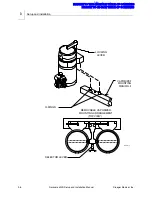
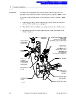
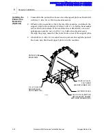
Page 20: ... at the absorber install the short pilot line which has quick connect fittings on both ends as follows 1 Connect one end of the pilot line to the fitting mounted on the rear of the pipe extending from the absorber top assembly 2 Connect the other end of the pilot line to the BREATHING PRESSURE interface underneath the rear panel of the ventilator box SU00603A QUICK CONNECT FITTINGS REAR PANEL OF V...

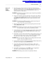
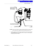
Page 21: ...ber is self closing You can leave it unused when installing the long pilot line for Y piece monitoring 2 Connect the Luer fitting on the other end of the pilot line to a Luer fitting on either the patient Y piece or a 15 mm adapter on the patient side of the Y piece 3 Using the four plastic hose clips attached to the pilot line mount the pilot line on either of the breathing hoses leading to the Y...

Page 22: ... only fits into the housing one way 2 Align the key on the sensor cord connector with the keyway on the AUTO BAG SELECTOR interface underneath the ventilator box Then push the connector in until it snaps into place SU00602 INTERFACE CABLE SENSOR CORD CONNECTOR MANUAL AUTOMATIC SELECTOR VALVE REAR PANEL OF VENTILATOR BOX 2 VOLUME SENSOR OXYGEN SENSOR BREATHING PRESSURE AUTO BAG SELECTOR MANUAL AUTO...

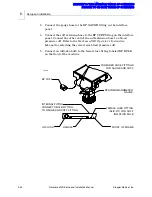
Page 23: ...tective covering from the sensor housing 4 Perform an oxygen sensor calibration as described in Operation Oxygen Monitoring in the Narkomed GS Operator s Manual 5 Insert the sensor assembly into the inspiratory valve dome by pressing it into place SU00601 SENSOR HOUSING INSPIRATORY VALVE DOME INSPIRATORY VALVE DOME PLUG P N 4106387 SENSOR CORD CONNECTOR 2 VOLUME SENSOR OXYGEN SENSOR BREATHING PRES...

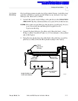
Page 24: ...the flow sensor and join the other end of the hose to the expiratory valve Ensure that the expiratory valve is oriented as shown in the illustration below 3 Connect the sensor plug to the VOLUME SENSOR interface on the rear panel of the ventilator box SU00009A FLOW SENSOR BRACKET ABSORBER ASSEMBLY EXPIRATORY HOSE TERMINAL EXPIRATORY VALVE CONNECTOR HOSE ULTRASONIC FLOW SENSOR SENSOR PLUG 2 RETURN ...

Page 25: ...er assembly on the block below the APL valve WARNING To avoid confusion between hose terminals on the absorber system and the Bain Circuit Adapter always remove the Bain Circuit Adapter from the absorber mount when the Bain Circuit Adapter is not in use TO BREATHING PRESSURE MONITOR INTERFACE PANEL OXYGEN SENSOR 22MM M 15MM F EXPIRATION TERMINAL BAIN CIRCUIT BAIN CIRCUIT HOSE BARB FOR FRESH GAS HO...

Page 26: ...o equipped 2 Slip the Bain Circuit Adapter mounting stud into the absorber pole 3 Tighten the set screw on the absorber pole to lock the Bain Circuit Adapter in place OXYGEN SENSOR BAIN CIRCUIT BREATHING BAG MOUNT 19 MM SCAVENGER HOSE P N 9995230 CONNECTS TO 19MM TERMINAL ON SCAVENGER 22MM HOSE P N 9995123 CONNECTS TO VENTILATOR HOSE TERMINAL ON VENTILATOR BELLOWS ASSEMBLY BAIN CIRCUIT HOSE BARB F...

Page 27: ...ARNING Breathing bags attached to the Bain Circuit Adapter s 22 mm terminals must comply with current ANSI standards 4 Connect the 19 mm scavenger hose between the 19 mm terminal at the rear of the APL valve marked SCAVENGER HOSE and the 19 mm terminal on scavenger 5 If applicable connect a 22 mm hose between the terminal on the rear of the manual automatic selector valve and the VENTILATOR HOSE t...

Page 28: ...resh gas outlet of the anesthesia machine 4 Insert the oxygen sensor into the port on top of the adapter WARNING If the oxygen sensor is removed the oxygen sensor port must be closed with the oxygen sensor port plug 5 Attach the non rebreathing circuit fresh gas hose to the adapter s barbed fitting For non rebreathing circuits equipped with a 15 mm fresh gas connector cut off the connector and pre...

Page 29: ... installing the scavenger and the absorber 1 Connect a 19 mm scavenger hose between the 19 mm terminal marked SCAVENGER HOSE on the rear of the APL valve and the 19 mm terminal marked SCAVENGER HOSE on the right side of the scavenger WARNING The 19 mm scavenger hose leading from the absorber must not be pinched kinked or blocked in any manner VENTILATOR RELIEF VALVE 19MM SCAVENGER HOSE TERMINAL VA...

Page 30: ...nnections are described below CAUTION Take special care not to accidentally force 19 mm scavenger hoses over 22 mm breathing hose terminals Carefully follow the hose connection instructions for installing the scavenger and the absorber 1 Connect a 19 mm scavenger hose between the 19 mm terminal marked SCAVENGER HOSE on the rear of the APL valve and the 19 mm terminal marked SCAVENGER HOSE on the r...

Page 31: ... 19 mm scavenger hose between the 19 mm terminal labeled EXHAUST on the bottom of the scavenger and the hospital exhaust system grill adapter SU14717B TO HOSPITAL EXHAUST SYSTEM 19MM SCAVENGER HOSE P N 9995230 ABSORBER POLE VENTILATOR RELIEF VALVE 19MM SCAVENGER HOSE TERMINAL SCAVENGER INTERFACE FOR NON ACTIVE SYSTEMS 19MM SCAVENGER HOSE P N 9995230 APL VALVE RETURN TO CD ROM TABLE OF CONTENTS RET...

Page 32: ...socket screws and lock washers If the machine was ordered with a manual sphygmomanometer use a 20 x d in button head socket screw through the gauge mount at the lower front corner of the support plate 3 3 Install two 20 x 1 in socket head cap screws through the patient line boom arm block and support plate into the machine SU87030 SUPPORT PLATE PATIENT LINE BOOM ARM 1 4 20 X 7 8 IN BUTTON HEAD SOC...

Page 33: ...the threads of the gauge mount located at the boom arm support plate on the left side of the anesthesia machine 2 Screw the manual sphygmomanometer gauge mounting ring tightly onto the gauge mount oriented with the gauge facing forward GAUGE MOUNT THREADED MOUNTING RING MANUAL SPHYGMOMANOMETER GAUGE SU87032 RETURN TO CD ROM TABLE OF CONTENTS RETURN TO THIS MANUAL S TABLE OF CONTENTS ...

Page 34: ...cuff Refer to the Narkomed GS Operator s Instruction Manual for selecting the correct size blood pressure cuff 5 Connect an inflation bulb to the female luer fitting labeled BP BULB on the front of the machine SU00605 THREADED HOSE FITTINGS FOR GAUGE AND CUFF INTERNAL PIPING CONNECTS BULB FITTING TO GAUGE AND CUFF FITTING FEMALE LUER FITTING SLIP FIT FOR CUFF INFLATION BULB SPHYGMOMANOMETER GAUGE ...

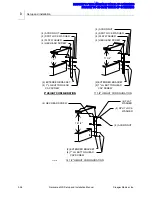
Page 35: ...configuration and install the second shelf assembly as illustrated For the 3 in and 6 in configurations the second shelf assembly is installed directly to the machine For the 9 in 11 in and 14 in configurations two extender brackets must be used SU87029 6 1 4 HEIGHT CONFIGURATION 4 1 LG BUTTON HEAD CAP SCREW 6 1 4 3 1 2 HEIGHT CONFIGURATION 4 1 LG BUTTON HEAD CAP SCREW SHELF ASSEMBLY 3 1 2 RETURN ...

Page 36: ...SCREW 4 1 LG BUTTON HEAD CAP SCREW 4 FLAT WASHER 4 SPLIT LOCK WASHER 4 ACORN NUT 2 EXTENDER BRACKET 9 4 HEX HEAD SCREW 4 FLAT WASHER 4 SPLIT LOCK WASHER 4 ACORN NUT 4 1 LG BUTTON HEAD CAP SCREW 2 EXTENDER BRACKET 11 3 4 4 1 LG BUTTON HEAD CAP SCREW 2 EXTENDER BRACKET 14 1 2 4 HEX HEAD SCREW 4 ACORN NUT 4 SPLIT LOCK WASHER 4 FLAT WASHER RETURN TO CD ROM TABLE OF CONTENTS RETURN TO THIS MANUAL S TAB...

Page 37: ... Position the shelf extender at the right side of the machine and attach the extender to the ventilator box with two 8 32 x d in button head screws and one 5 16 24 x e in button head screw 3 Reinstall the clip board hook with two 10 32 x in button head screws 4 If the machine is equipped with a vapor box push pull bar reinstall the bar with four 10 32 x f in socket head cap screws If the machine i...

Page 38: ... X 7 8 SS 2 SCREW BUTTON HD SKT 8 32 X 3 8 SS BO CONFIGURATION WITH PUSH PULL BAR SHELF EXTENDER CLIP BOARD HOOK PUSH PULL BAR 1 SCREW BUTTON HD SKT 5 16 24 X 5 8 SS BO 2 SCREW BUTTON HD SKT 8 32 X 3 8 SS BO CONFIGURATION WITHOUT PUSH PULL BAR SU87027 SHELF EXTENDER CLIP BOARD HOOK 6 SCREW BUTTON HD SKT 10 32 X 1 2 SS BO RETURN TO CD ROM TABLE OF CONTENTS RETURN TO THIS MANUAL S TABLE OF CONTENTS ...

Page 39: ... onto the mounting clips Be sure that the clips engage both mounting rails on the outlet strip housing 3 Connect the outlet strip power cord to a hospital grade outlet only DO NOT connect the power cord to the convenience receptacles on the anesthesia machine SU87031 REAR VIEW OF ANESTHESIA MACHINE WHEN USING THIS OUTLET STRIP UL MOUNTING CLIP 2X MOUNTING SCREW 2X P N HW02014 OUTLET STRIP RETURN T...

Page 40: ...RETURN TO CD ROM TABLE OF CONTENTS RETURN TO THIS MANUAL S TABLE OF CONTENTS ...

Page 41: ...Setup and Installation Manual 4 Gas Supply Connections Section contents Gas Supply Connections 4 2 Connecting the Cylinders 4 3 Connecting the Pipelines 4 4 RETURN TO CD ROM TABLE OF CONTENTS RETURN TO THIS MANUAL S TABLE OF CONTENTS ...

Page 42: ...ing Each connection valve gauge and flowmeter is labeled and color coded for the appropriate gas Color codes for the USA ISO and Germany are shown in the following table N2O YOKES 3RD GAS YOKE O2 YOKE PIPELINE SUPPLY GAS FITTINGS SU87024 GAS SYSTEM COLOR CODING GAS MARKING USA ISO GERMANY Air AIR Yellow Black White Checkered Yellow Carbon Dioxide CO2 Gray Gray Black Nitrous Oxide N2O Blue Blue Gra...

Page 43: ...oke Using more than one washer could cause leakage of the cylinder gas and compromise the pin indexing system 2 Verify the presence and integrity of the two index pins below the gas inlet WARNING Check cylinder yokes for the presence of two index pins each time a cylinder is attached to the machine 3 Insert the head of a gas cylinder with matching gas into the yoke from below so that the gas outle...

Page 44: ...nitrous oxide For this reason oil and grease must never come in contact with pipelines cylinders cylinder valves gauges fittings etc which conduct oxygen or nitrous oxide within the machine For further information regarding safety precautions in the use of medical gases consult Compressed Gas Association pamphlet P 2 and appropriate sections of National Fire Protection Association Standard 99 YOKE...

Page 45: ... caused accidents when during assembly an oxygen fitting has been placed on one end of the hose and a nitrous oxide fitting on the other end 2 Connect the other end of each supply hose to the appropriate functioning hospital pipeline outlet 3 Check the pipeline pressure gauge on the front of the Narkomed GS for sufficient pipeline pressure 50 55 psi O2 NIST GAS FITTING AIR NIST GAS FITTING O2 DISS...

Page 46: ...RETURN TO CD ROM TABLE OF CONTENTS RETURN TO THIS MANUAL S TABLE OF CONTENTS ...

Page 47: ...up and Installation Manual 5 Power up and System Configuration Section contents Connecting the Narkomed GS to Electrical Power 5 2 Power Up Diagnostics Test 5 3 RETURN TO CD ROM TABLE OF CONTENTS RETURN TO THIS MANUAL S TABLE OF CONTENTS ...

Page 48: ...t with electrical code for this usage must be installed on the cord by a qualified electrician Connect the Narkomed GS to electrical power as follows 1 Verify that the Narkomed GS s SYSTEM POWER switch is set to STANDBY 2 Enable all circuit breakers by placing them in the set pushed in position 3 Unwrap the power cord and connect its female end to the power inlet connector 4 Plug the power cord in...

Page 49: ...tion 2 Verify that the battery in use AC POWER FAIL indicator on the main switch panel remains unlit 3 Verify that all circuit breakers remain in the set pushed in position NARKOMED GS COPYRIGHT 1996 NAD INC VERSION NMGSPOD SOFTWARE ID XXXX DIAGNOSTIC TESTS FIRMWARE PASS RAM PASS VIDEO PASS A D CONVERTER PASS AUDIO PRIMARY PASS BACKUP PASS SERIAL I O PASS CLOCK PASS NON VOLATILE MEMORY PASS PREVEN...

Page 50: ...RETURN TO CD ROM TABLE OF CONTENTS RETURN TO THIS MANUAL S TABLE OF CONTENTS ...

Page 51: ...corresponding service manual Therefore any revision notices on these pages will reflect the revision level at which they occurred in the service manual and are not related to the revision level of this setup and installation manual RETURN TO CD ROM TABLE OF CONTENTS RETURN TO THIS MANUAL S TABLE OF CONTENTS ...

Page 52: ...RETURN TO CD ROM TABLE OF CONTENTS RETURN TO THIS MANUAL S TABLE OF CONTENTS ...

Page 53: ...our supervisor immediately if any equipment is found to be out of calibration In the space provided at the bottom of the PMC checklist form record the Model and ID number of all calibrated test equipment used In the space provided at the bottom of the PMC checklist form record the Model and ID number of all calibrated test equipment used Also record the calibration due dates Examples are multimete...

Page 54: ... or equivalent Breathing System Leak Test Device P N S010159 or equivalent PDM Suction Adapter P N 4115038 Scavenger Adapter P N 4108114 NIBP w Luer Test Adapter P N 4116111 001 Pressure Monitor Test Adapter P N 4115043 or equivalent Key test equipment and materials illustrations are shown on following pages RETURN TO CD ROM TABLE OF CONTENTS RETURN TO THIS MANUAL S TABLE OF CONTENTS ...

Page 55: ...RE continued 6 3 SP15001 4114807 PRESSURE TEST ASSEMBLY WITH ADAPTERS 4114830 002 4114830 001 4114830 004 4114830 003 4114830 006 4114830 005 RETURN TO CD ROM TABLE OF CONTENTS RETURN TO THIS MANUAL S TABLE OF CONTENTS ...

Page 56: ...NUTE VOLUMETER 5 10 100 ml vol min 15 Liter 200 300 400 500 600 700 800 900 S000081 FLOW METER TEST STAND 8401892 SIEMENS TEST LUNG TEST TERMINAL 4104389 TEST TERMINAL ADAPTER RETURN TO CD ROM TABLE OF CONTENTS RETURN TO THIS MANUAL S TABLE OF CONTENTS ...

Page 57: ...H GAS OUTLET VOLUME TEST DEVICE 4115041 FRESH GAS LEAK TEST DEVICE TEST TERMINAL TEST TERMINAL S010159 BREATHING SYSTEM LEAK TEST DEVICE 4115042 VOLUMETER FRESH GAS HOSE ADAPTER RETURN TO CD ROM TABLE OF CONTENTS RETURN TO THIS MANUAL S TABLE OF CONTENTS ...

Page 58: ...R ADAPTER 4115038 PDM TO PATIENT SUCTION ADAPTER ADAPTER FOR TOP PORT ON CAPNOMED FLOW METER 4110709 LUER F 1 8 MPT 4108114 SCAVENGER ADAPTER 4116111 001 NIBP W LUER TEST ADAPTER AVENGER RETURN TO CD ROM TABLE OF CONTENTS RETURN TO THIS MANUAL S TABLE OF CONTENTS ...

Page 59: ...tion levels The first list in the Recommendation Guidelines is a reference chart for machine certification based on equipment status The second is an abbreviated summary of all DMI Recommendations and Failure Codes including the Condition Number Equipment Condition Recommended Corrections Certification Code and Tests Affected when applicable There is also a matrix classified as Failure Codes which...

Page 60: ...ke precedence over Certified with Recommendations For example A Narkomed 2B could have DMI Recommendation number 21 and Failure Code 61 1 that apply 21 No ventilator pressure limit control Code is B 61 1 Enflurane agent is unavailable to test Code is BC Correct certification for this machine is BC which means CONDITIONALLY CERTIFIED WITH RECOMMENDATIONS A Narkomed 4 could have DMI Recommendation n...

Page 61: ...27 on the vaporizer and issue a departmental alert The TSR shall also seek permission from the equipment operator to remove the failed vaporizer from the machine and apply a replacement vaporizer or an adapter block onto the mount All SOIL 1 vaporizers must be removed from service for machine to receive certification 6 Perform the vapor concentration test on all Dräger vapor vaporizers in accordan...

Page 62: ...e of PM Certification next to NEXT VISIT DUE If certification level is D machine shall not receive a PM CERTIFICATION label Any machine not receiving a PM Certification label shall receive a WARNING NOT CERTIFIED label P N 4114857 This label shall be placed at a prominent location on the left side of the machine after all other previous PMC and Vigilance Audit Validation labels have been removed 1...

Page 63: ... a Desflurane vaporizer 6 2 1 2 Unplug the machine s AC power cord and plug the power cord of the safety analyzer into this AC receptacle NOTE Do not plug the safety analyzer power cord into a line isolation monitor circuit as inaccurate readings may occur NOTE The BIOTECH 501 PRO will automatically test the source outlet for open ground or ground resistance of 31 Ohms or higher reverse polarity o...

Page 64: ...t the respiratory volume sensor cord to the interface panel 6 2 3 Chassis Leakage Current 6 2 3 1 Apply the analyzer test lead to a cylinder yoke bolt 6 2 3 2 Set the safety analyzer to the CHASSIS LEAKAGE CURRENT position 6 2 3 3 Record the total leakage current with the Polarity and Ground switches set as follows Ground Polarity Normal Normal Open Normal Open Reversed Normal Reversed 6 2 3 4 Ver...

Page 65: ... 6 4 1 Press and hold the Oxygen High Limit key and the Volume Low Limit key and then press the arrow up key 6 4 2 The Main Service Screen shall appear 6 4 3 Select and enter the Service Log 6 4 4 Verify any pertinent information from the Service Log Contact the Draeger Medical Inc Technical Service Department if necessary 6 4 5 Press EXIT to return to the Main Service screen 6 4 6 Select the SRVC...

Page 66: ...ressure sensor line 6 5 9 Pressurize the circuit to 50 cm H2O and allow the Current Value to stabilize 6 5 10 Press the SPAN key and verify that the new span values are stored 6 5 11 Release the pressure disconnect the manometer and test fixture and reconnect the breathing pressure sensor line to the absorber 6 5 12 Press EXIT to return to the Main Service screen 6 5 13 Press EXIT to return to nor...

Page 67: ...r under the valve in good condition ___ Y 6 6 9 3 Remove the Spiromed sensor 6 6 9 4 Is the washer under the sensor in good condition ___ Y 6 6 9 5 Locate the four lateral holes at the sides of the Spiromed sensor marked by arrows CAUTION Use only Sensor Lubrication Kit P N 2218180 for the following procedure 6 6 9 6 Dip the tip of the pipette into the lubricant and draw lubricant into the pipette...

Page 68: ...ygen flow control valve is closed 6 7 3 Disconnect all pipeline supply hoses at the wall outlets 6 7 4 Open then close and remove each cylinder and if applicable remove the yoke plug from each additional yoke assembly 6 7 5 Note the reading on each the cylinder pressure gauge and start a stop watch 6 7 6 Are the two 2 yoke index pins installed securely in each yoke ___ Y 6 7 7 Is the proper gas I ...

Page 69: ...apply 50 cm H2O of pressure to the system and start a stopwatch Is it possible to turn on either the left or right vapors ___ N 6 8 1 12 After thirty 30 seconds is the center vaporizer test pressure equal or greater than 40 cm H2O ___ Y Turn off the center mounted vaporizer 6 8 1 13 If applicable turn on the right mounted vaporizer to the first graduated marking Reapply 50 cm H2O of pressure to th...

Page 70: ...0 ml min flowmeter S000081 to the test terminal 6 8 4 4 Turn up the Oxygen flow until the system pressurizes to 30 cm H2O Adjust the APL valve as necessary to maintain 30 cm H2O 6 8 4 5 Is the value indicated on the flowmeter within 0 to 60 ml min ___ Y 6 8 4 6 Close APL valve 6 8 4 7 Remove all test equipment 6 8 5 Inspiration Valve Leak 6 8 5 1 Turn the System Power switch to Standby 6 8 5 2 Con...

Page 71: ...um PEEP indicated on the test gauge within 15 to 22 cm H2O ___ Y 6 8 6 11 Place the PEEP bypass in the OFF position 6 8 6 12 Does the PEEP return to 3 cm H2O ___ Y 6 8 6 13 Adjust the absorber PEEP valve counterclockwise to its minimum position 6 8 6 14 Does the PEEP return to 3 cm H2O ___ Y 6 8 6 15 Close the O2 flow control valve 6 8 6 16 Remove the test equipment and reconnect the pilot line to...

Page 72: ...ove the test equipment and reconnect the pilot line to the Bain Circuit 6 9 OXYGEN ANALYZER 6 9 1 Press the CAL key NOTE Make sure that the sensor has stabilized in ambient air for several minutes 6 9 2 After calibration is completed is the O2 concentration 21 ___ Y 6 9 3 The warning message INSP O2 LOW shall appear on the central alarm display and a continuous alarm shall sound 6 9 4 Press the Al...

Page 73: ...trol valve ___ Y Oxygen Helium specifications are given 25 O2 Cylinder content deviations will affect this value The expected concentration values can be obtained by replacing the 25 O2 value given for O2 HE with the actual cylinder content as follows 2 l min O2 HE x 25 4 l min O2 x 100 6 l min Total Flow O2 6 10 3 This Section Intentionally Left Blank 6 10 4 This Section Intentionally Left Blank ...

Page 74: ...o adjust the flow of Nitrous Oxide over the full range of the flowmeter ___ Y 6 10 8 Oxygen Ratio Control 6 10 8 1 Open the Nitrous Oxide flow control valve to the stop position 6 10 8 2 After the value stabilizes is the O2 concentration 21 to 29 ___ Y 6 10 8 3 Set the Oxygen flow to 2 l min 6 10 8 4 After the value stabilizes is the O2 concentration 21 to 29 ___ Y 6 10 8 5 Set the Oxygen flow to ...

Page 75: ...11 1 1 Configure the test gauge P N 4114807 using a N2O nut stem DISS connector P N 4114830 004 on the hose and N2O DISS body connector P N 4114830 003 on the valve body side If the machine is configured with CSA style fittings reverse the position of the connectors 6 11 1 2 Connect the test fixture hose to the machine s Nitrous Oxide pipeline inlet 6 11 1 3 Connect the Nitrous Oxide pipeline supp...

Page 76: ...ture 6 11 2 4 Set the Air flow to 4 l min 6 11 2 5 Depress the push button on the test device 6 11 2 6 Release the push button After the pressure decay stabilizes is the regulator output pressure within tolerance given in the following table ___ Y NOTE If a pressure decrease does not occur either the hospital s supply pressure is too low or the regulator pressure is set too high 6 11 2 7 Remove th...

Page 77: ...tor output pressure within the tolerance given in the following table ___ Y NOTE If a pressure decrease does not occur either the hospital s supply pressure is too low or the regulator pressure is set too high 6 12 LOW O2 SUPPLY Six Month Service Interval Due Date _____ 6 12 1 Close the Oxygen cylinder valve and drain all Oxygen pressure 6 12 2 Depress the push button on the test device 6 12 3 Adj...

Page 78: ...ontrol valves Nitrous Oxide Bypass flow and Minimum Oxygen flow specifications are given 50 psi Pipeline pressure deviations may affect these tests 6 14 PRESSURE MONITOR 6 14 1 Disconnect the breathing pressure sensor line from the absorber 6 14 2 Connect a PDM Adapter P N 4115043 and test pressure gauge to the breathing pressure sensor line 6 14 3 Adjust the test pressure to 0 cm H2O 6 14 4 Simul...

Page 79: ...Turn on the ventilator on using the ON OFF knob 6 15 5 If applicable does the FAULT indicator turn on Y 6 15 6 Set the AUTO MAN selector switch to AUTO 6 15 7 Does the FAULT indicator turn off Y 6 15 8 Set the FREQUENCY to 10 BPM 6 15 9 Press and hold the EXTENDED RANGE switch and set the I E ratio to 2 1 Using a stopwatch time the extended I E ratio Is the inspiratory time within 3 6 to 4 4 secon...

Page 80: ...ed with an ultrasonic flow sensor 6 15 25 Open the Y piece 6 15 26 Turn the ventilator off and press the ALL STBY key to clear alarms 6 15 27 Turn the ventilator on and start a stop watch 6 15 28 Does APNEA VOLUME appear as a Caution within 13 to 17 seconds ___ Y 6 15 29 Attach a 3 liter breathing bag to the Y piece NOTE Bag should be placed on a flat horizontal surface to reduce artifact volume 6...

Page 81: ...__ Y 6 16 15 Is the PEEP value displayed on the monitor 0 to 3 cm H2O ___ Y 6 16 16 Remove the breathing bag from the Y piece and replace it with a test lung 6 16 17 Adjust the Oxygen flow to 300 ml min 6 16 18 Adjust the Tidal Volume to 200 ml 6 16 19 Does the bellows stop adjust smoothly and engage properly ___ Y 6 16 20 Adjust the INSPIRATORY FLOW to fully compress the bellows 6 16 21 Is the Ti...

Page 82: ...1 BPM 6 17 18 Set the I E RATIO to 1 1 6 17 19 Set the Inspiratory Flow to MAX 6 17 20 Is the drive gas leakage indicated during the inspiratory phase 0 to 50 ml min ___ Y 6 17 21 Remove the test equipment and reattach the ventilator hose to the VENTILATOR HOSE terminal 6 17 22 Set AUTO BAG valve to BAG 6 17 23 Press the Alarms All Standby key 6 18 BELLOWS PEDIATRIC INTERNAL If applicable 6 18 1 R...

Page 83: ... environment contains a significant amount of dust and lint the cleaning frequency must be increased to compensate for these conditions 6 19 1 OPEN RESERVOIR SCAVENGER CLEANING 6 19 1 1 Remove the scavenger hoses and drain all accumulated moisture Inspect all scavenger hoses for deterioration and replace as needed 6 19 1 2 Disconnect the hospital vacuum source from the scavenger 6 19 1 3 Cleaning ...

Page 84: ...IR PRESSURE TESTING 6 19 2 1 Activate the Scavenger vacuum supply 6 19 2 2 Turn the scavenger needle valve fully clockwise closed 6 19 2 3 Uncap the hose barb adapter at the rear of the scavenger and connect a test pressure monitor to the hose barb on the adapter using a PDM Suction Adapter P N 4115038 If the scavenger does not contain a hose barb adapter install a scavenger adapter P N 4108114 be...

Page 85: ...sed to turn the valve Be careful not to damage the valve s fragile disk 6 20 1 5 Remove any accumulated lint or dust from the valve with a soft brush The valve may be further cleaned with a low flow of Air or Oxygen The scavenger body can be cleaned with a moist cloth 6 20 1 6 Reinstall the valve into the housing making sure that it is threaded all the way into the housing and that the plastic was...

Page 86: ...ioration then reinstall or replace as needed All under sized or single use bags must be replaced with 5 liter reusable style reservoir bag 6 21 1 3 Remove the plastic valve cover on the front surface of the scavenger body by turning it in a counter clockwise direction 6 21 1 4 Remove the valve and washer from the scavenger body by turning it counter clockwise A needle nose pliers may be used to tu...

Page 87: ... 2 2 Turn the scavenger needle valve fully clockwise closed 6 21 2 3 Install a scavenger adapter P N 4108114 between the 19 mm hose terminal on the scavenger and the scavenger hose 6 21 2 4 Connect a test pressure monitor to the hose barb on the adapter using a PDM Suction Adapter P N 4115038 6 21 2 5 Set the AUTO MAN valve to the BAG position 6 21 2 6 Connect a 22mm breathing hose between the abs...

Page 88: ...he female Luer fitting labeled BP BULB on the front of the machine 6 23 2 Insert an NIBP Luer Test Adapter P N 4116111 001 inline between the blood pressure cuff and the extension hose 6 23 3 Wrap the blood pressure cuff around an E cylinder 6 23 4 Hand pump the squeeze bulb until pressure of 200 mm Hg is indicated on the test gauge and start a stop watch 6 23 5 Does the Sphygmomanometer indicate ...

Page 89: ...pilot line is connected between the machine interface and absorber 6 24 9 Verify the Oxygen sensor is removed from the inspriatory valve dome adapter 6 24 10 Verify the inspriatory valve dome is plugged 6 24 11 Unplug the machine s AC power cord Is the AC PWR FAIL LED lighted ___ Y Press and hold the BATTERY TEST button Is green Battery Test LED lighted ___ Y 6 24 12 Plug the power cord back into ...

Page 90: ...RETURN TO CD ROM TABLE OF CONTENTS RETURN TO THIS MANUAL S TABLE OF CONTENTS ...

Page 91: ...RETURN TO CD ROM TABLE OF CONTENTS RETURN TO THIS MANUAL S TABLE OF CONTENTS ...

Page 92: ...cal Inc 3135 Quarry Road Telford PA 18969 Tel 215 721 5404 800 462 7566 Fax 215 721 9561 Web www draegermedical com Printed in the U S A RETURN TO CD ROM TABLE OF CONTENTS RETURN TO THIS MANUAL S TABLE OF CONTENTS ...
Reviews: