24
Technical Manual
|
Dräger Polytron
®
8000 Series
Installation
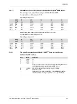
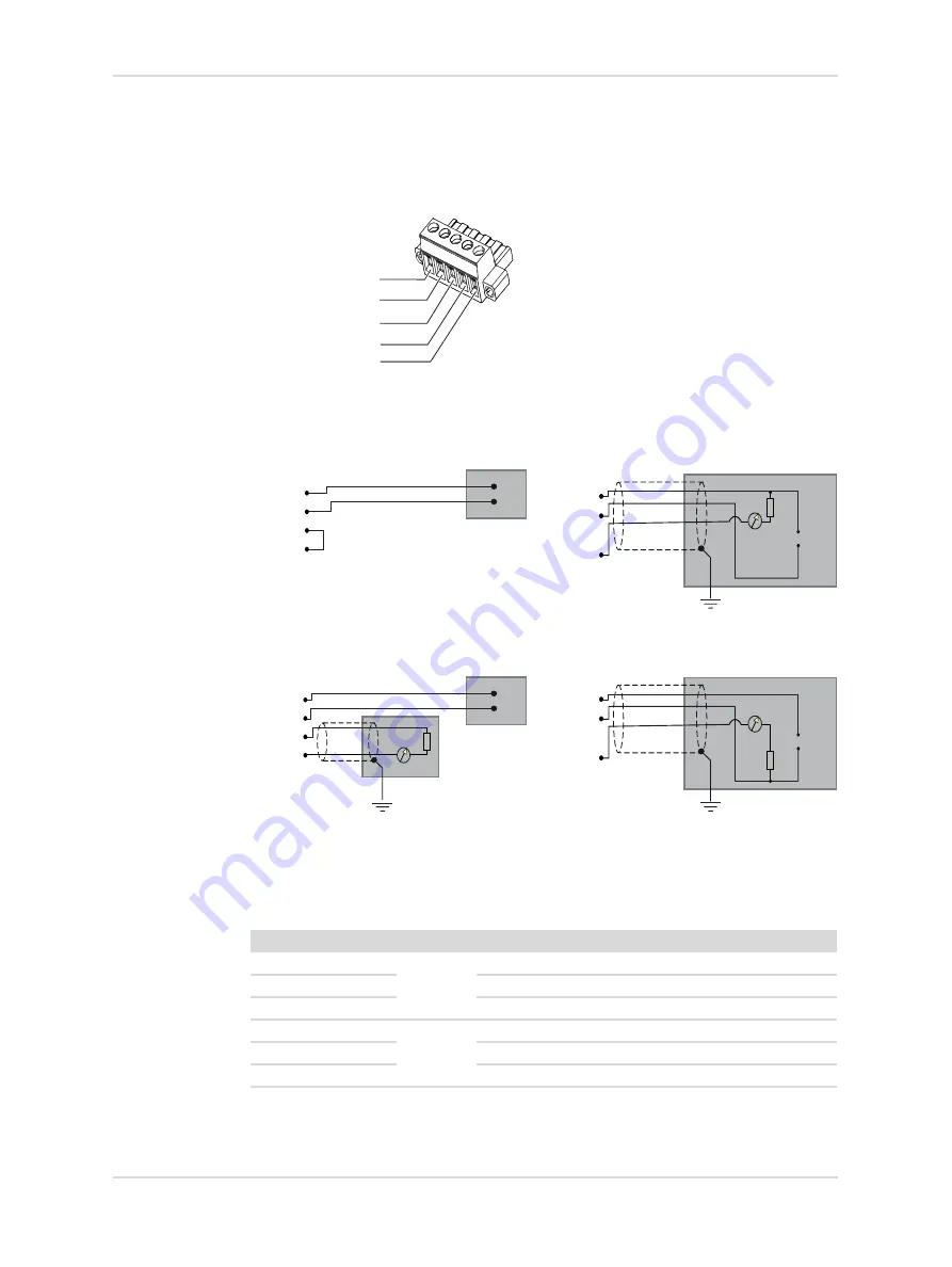
5-pin connector for 4-20 mA and HART
®
connections
Galvanic separation of a separate power supply and analog signal output is not
possible (pin 2 and 3 are connected within the 5-pin connector).
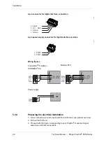
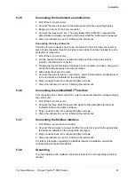
Wiring figures
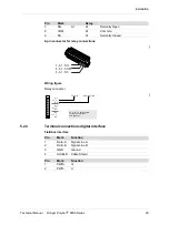
Relay connector
The relay labels (NO, COM, NC) represent the default state (normally energized) of
all relays while the instrument is powered.
44798
Stand-alone, relay only
4-20 mA / HART
®
(Current sink)
4-20 mA / HART
®
(Separate power)
4-20 mA / HART
®
(Current source)
Pin
Mark
Relay
1
NO
FLT
Fault Normally
Open
2
COM
Fault Common
3
NC
Fault Normally
Closed
4
NO
A2
A2 Normally
Open
5
COM
A2
Common
6
NC
A2 Normally
Closed
3 - PWR-
2 - PWR-
1 - PWR+
4 - 4-20mA
5 - PE
PWR+
PWR-
PWR-
4-20 mA
PE
VDC
+
-
VDC
+
-
mA
PWR+
PWR-
PWR-
4-20 mA
PE
mA
PWR+
PWR-
PWR-
4-20 mA
PE
VDC
+
-
VDC
+
-
mA
PWR+
PWR-
PWR-
4-20 mA
PE

