background image


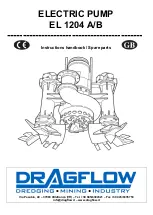
ELECTRIC PUMP EL 1204 A/B 


INSTRUCTIONS HANDBOOK 

_________________________

____________________________________________________________________

____________________________________________________________________________

Ed. 12/11____


_________________________________________________________________________________ 


pg. 


PRESENTATION 


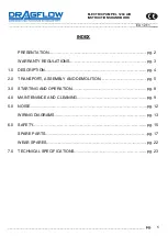
This instructions manual has been conceived and structured for rapid and easy consultation, thanks to the 
index ordered by subjects, and explanatory figures and tables. 


GENERAL WARNINGS 


This instructions manual must be studied by the owner of the machine, the technical personnel within the 
factory, the operators, that is, all those that will be using the machine, the maintenance technician. 
The manual is an integral part of the machine and contains information on its use, technical characteristics, as 
well as instructions for handling, installation, assembling, regulation and maintenance. 
It also contains a section for trouble-shooting, if necessary, and for the ordering of spares. 
The 

DRAGFLOW S.r.l.

 technicians are always available, by telephone, fax or e-mail, to supply all the 

explanations that may be needed. 
 

This manual: 

-


must be considered as integral part of the machine until it is taken to the breakdown yard; 

-


must be kept in an easily accessible place and suitable for its preservation;


-


must be consulted each time that there are problems or doubts on the operation of the machine; 

-


must be carefully followed for whatever regards the necessary maintenance operations set out in it.


In case it is lost, apply for a copy directly from 

DRAGFLOW S.r.l.


DRAGFLOW S.r.l.

 reserves the right to carry out all modifications to update the machine or instructions 

manual according to the technological progress and the state of the art. 
This constitutes no obligation to carry out modifications to the machines that have already been sold. If the 
machine is ceded to a third party, it is recommended that of the instructions manual follow it. 


DRAGFLOW S.R.L. RETAINS ITSELF FREE FROM LIABILITY OF ANY KIND, AND ESPECIALLY FOR: 

-


improper use of the machine; 

-


use of the machine by personnel not trained to used it; 

-


power supply defects; 

-


maintenance defects; 

-


unauthorized and unforeseen modifications; 

-


use of spares that are not original or not specific for the model; 

-


non observance of the instructions; 


The uses of the machine for different purposes are to be considered dangerous for the operator and for the 
machine. Likewise, modalities of installation and utilizations different from that indicated in the present manual 
could cause damage to persons and/or to the machine itself.


Summary of Contents for EL 1204 A

Page 1: ...ELECTRIC PUMP EL 1204 A B Instructions handbook Spare parts Via Pasubio 40 37069 Villafranca VR Tel 39 045 6304521 Fax 39 045 6335758 info dragflow it www dragflow it...

Page 2: ...______Ed 12 11____ _________________________________________________________________________________ pg 1 INDEX PRESENTATION pg 2 WARRANTY REGULATIONS pg 3 1 0 DESCRIPTION pg 4 2 0 TRANSPORT ASSEMBLY...

Page 3: ...machine until it is taken to the breakdown yard must be kept in an easily accessible place and suitable for its preservation must be consulted each time that there are problems or doubts on the operat...

Page 4: ...As soon as the spare is ready The Client will make the defective part available to DRAGFLOW S r l The warranty does not apply to those parts that result defective because of incorrect use handling or...

Page 5: ...entially made up of a cylindrical pump casing 3 inside of which is housed an electrical motor 4 The upper part 2 is completely water tight and contains the terminal box for connection to the electric...

Page 6: ...pump is placed inside the crate as seen in Fig 3 it must be freed from the packing and lifted with ropes hooked to the appropriate lifting plate A Fig 2 Fig 3 INSTALLATION 1 Connect the delivery pipe...

Page 7: ...mpletely insulated cable comes out sufficiently to be connected to the terminal box 85 Tighten the screws 4 until the cable 1 lock rests on the upper cover 77 making sure that the composed pack is suf...

Page 8: ...TLING Before doing anything on the pump be sure to disconnect the electrical supply and disconnect the delivery pipes Warning the machine that is considered completely useless must be removed from the...

Page 9: ...Immerse the pump in clear water and push the START button 3 If any priming problems should come up stop the pump by pressing the STOP button and wait for about 30 seconds leaving it immersed until all...

Page 10: ...s of the machine switch off the general cutout switch and have an expert electrical technician come in or contact DRAGFLOW S r l Service for further details 4 0 MAINTENANCE AND CLEANING Warning mainte...

Page 11: ...n of the oil washing every 8 hours of operation by removing the plug labelled OIL Fig 10 For a total oil change or topping up the following steps have to be taken a It is good practice to empty the pu...

Page 12: ...nge on the suction side 50 Fig 12 after having removed the screws 52 With the flange pos 50 the lower wear plate 48 also will come down Remove the casing 45 Fig 12 after having removed the screws 42 E...

Page 13: ...machine should be temporarily placed out of service it is important to disconnect the electricity supply clean it and cover it to protect it from dust To put it back into service again follow the ins...

Page 14: ...______ ____________________________________________________________________________Ed 12 11____ _________________________________________________________________________________ pg 13 WIRING DIAGRAMS...

Page 15: ...__________________________________________________________________________________ ____________________________________________________________________________Ed 12 11____ ____________________________...

Page 16: ...__________________________________________________________________________________ ____________________________________________________________________________Ed 12 11____ ____________________________...

Page 17: ...n the paragraphs which deal with the use maintenance and repair All the organs in movement are segregated inside the pump structure The only rotating mechanical part is the agitator 54 Fig 16 that for...

Page 18: ...that expressed on the rating plate Fig 17 When starting check the correct connection of the phases the correct direction of rotation of the motor The direction of rotation is expressed on the rating...

Page 19: ...______________________________________________________________________ ____________________________________________________________________________Ed 12 11____ ________________________________________...

Page 20: ...__________________________________________________________________________________ ____________________________________________________________________________Ed 12 11____ ____________________________...

Page 21: ...__________________________________________________________________________________ ____________________________________________________________________________Ed 12 11____ ____________________________...

Page 22: ...1 F19801 MOTOR FAN 13 1 A6504069 PLUG 14 1 RR0001155 MAIN SHAFT ROTOR 15 1 A1501125 O RING 16 1 A1501094 O RING 17 2 A1501126 O RING 18 1 F21168 OIL CHAMBER 19 6 A2501006 SCREW 20 1 F42939 WEARING SP...

Page 23: ...GITATOR NUT 58 1 F19805 1 AGITATOR SPACER 59 1 A2518110 KEY 60 1 F24191 G DISCHARGE ADAPTER 200 61 8 A2510006 WASHER 62 8 A2501105 SCREW 64 1 A1002085 ROLLER BEARING 65 1 F42937 SEALS HOUSING 66 1 A65...

Page 24: ...ed in your workshop the following spare parts POS Q PART NUMBER DESCRIPTION 2A 1 A2087101 CABLE RUBBER SLEEVE 2B 6 A2527002 STEEL WASHER 2C 5 A1503130 RUBBER WASHER 11 1 A1001086 BALL BEARING 15 1 A15...

Page 25: ...tion class H class H Materials Main body spheroidal cast iron S6 Motor housing cast iron GS5 Wearing parts high chrome Main shaft austempering NiCrMo4 steel Seals Seals motor zone n 2 rubber lip seals...

Reviews: