background image

中龙集团

Dragon Group China Limited 


BIRD

®


www.dragongroupchina.com


www.chinaemall.biz


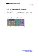
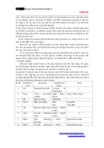
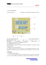
The meter has two rows of LED, the upper one is used to display the measurements 

(PV)  and  various  codes  of  parameters  ;the  lower  one  is  mainly  used  to  display  setting 

value  (SV),  the  output  value  (MV)  or  the  remained  time  of  running(TIME)  and  various 

parameters. When press the DISP SELECT button, the lower screen will show the items 

in the SV, MV, TIME order. When the meter is set as curve process controller (ctrl set to 

prog), TIME shows the remaining time of certain period of procedures. While the meter is 

set  to  constant  temperature  controller,  TIME  shows  cent  code.  In  some  special  type  of 

instrument,  TIME  shows  the  second  group  measured  value  or  special  meaning  of  input 

signals.   

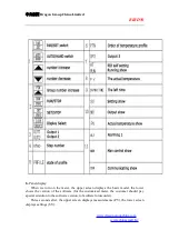
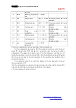
On  the  panel  of  the  meter,  there  are  two  digital  tubes  display  window:  PTN  and  STEP, 

and  four  indicative  lights:  PROFILE,  RUN  etc..  These  two  digital  tubes  and  four 

indicative lights are used to indicate the operation states of these curves. When the meter 

is set to curve procedures controller (ctrl set to prog), PTN is the display window of the 

No. of curve procedure. By pressing PTN button, we can select the curve which needs to 

run or be modified. When the curve is running, RUN blinks, STEP window shows the No. 

of the running curve. When running on the slopes of the increase, the indicator "/" is on. 

When running on the platform, indicator "-" is on. While running on the slope of decline, 

indicator "\" is on. 

When  the  meter  is  set  to  constant  temperature  controller,  the  two  display  windows: 

PTN and STEP, PROFILE, RUN, these four lights were off.   

OUT1 is used to indicate the working state of output 1. It is on when there is output.   

OUT2 is used to indicate the working state of output 2, It is on when there is output.   

SV lights: when the lower screen shows setting value, SV is on. MV lights: when the 

lower screen shows the output value, MV is on.   

TIME  lights:  the  lower  screen  shows  the  remained  time  of  the  operating  procedures, 

TIME is on. AL1 is used to indicate the working state of emergency. When the AL1 is in 

the state of alarm, the lights lit. MAN is used to indicate the state of manual work. When 

working  in  manually  state,  MAN  is  on.  COM  is  used  to  indicate  the  state  of 

communication. When the meter sends data, COM is on. AT is used to indicate the PID 

state. When the meter is in the state of PID, AT is on. OP3 is used to indicate the state of 

output 3, or used as special indicator in certain model. 

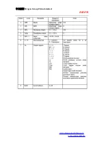
c. Button operation 


The meter have eight buttons, in which PTN, RUN/ PROG and SET/ PROG these three 

buttons are dedicated to a number of the setting of curve program parameters. When the 

meter is set to curve process controller (ctrl set to prog), PTN is used to set the number of 

curve  program.  SET/PROG  is  used  to  set  operating  parameters,  RUN/PROG  is  used  to 

start  the  program.  When  the  equipment  is  set  to  constant  temperature  controller,  RUN/ 

PROG, SET/ PROG are not working.   

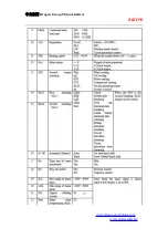
DISP / SELECT is the switch button. When we press DISP/ SELECT button, the lower 

screen  shows  settings  value,  the  output  value  or  the  remained  time  of  operation,  the 

corresponding indicator SV, MV, TIME are on.   

Summary of Contents for Bird AC-5K

Page 1: ...www chinaemall biz BGA Rework Station AC 5K Dragon Group China Limited Address Fuxin Building Office 12D No 318 Fuhua Road Shenzhen China 518000 Telephone 86 1 379 836 8284 86 755 83292149 Fax 86 755...

Page 2: ...upchina com www chinaemall biz Contents A BGA Rework Station B Installation C Safety Cautions D Introduction of Structure E Operation Steps F PLC Programmable logic Controller G Curve Program Controll...

Page 3: ...eatures of BGA a Types According to the encapsulation material BGA can be classified into the following types 1 PBGA Plastic BGA 2 CBGA Ceramic BGA 3 CCBGA Ceramic Column BGA 4 TBGA Tape BGA 5 CSP Chi...

Page 4: ...e design the assembly of PCB If many pieces of BGA gather on a small area of PCB it will cause the imbalance of PCB in the reflow oven If many big pieces of BGA gather on a certain area of PCB longer...

Page 5: ...d The ideal situation is no poor welding Poor welding may be caused by pollution or the uneven distribution of flux paste What s more warped PCB may also lead to poor welding Open circuit welding spot...

Page 6: ...tep can be omitted b Remove BGA If the BGA will not be reused and the PCB can endure high temperature we can use high temperature shorter heating period to remove it c Clean the pad Pad cleaning is ma...

Page 7: ...PBGA choose the higher reflux temperature For no clean solder paste its activity is lower than non no clean solder paste so the soldering temperature should not be too high and the soldering time shou...

Page 8: ...fire or explosion The PCB and other parts should be put on the PCB bracket 3 No vibration Handle it gently 4 Don t touch the heaters with your hands when it is working or you will get hurt 5 Don t use...

Page 9: ...u use the machine you must read the instructions attentively Note when the machine works it will produce some smell So ensure the comfortable healthy and safe operation environment please keep the air...

Page 10: ...orted high precision thermocouple to detect the top bottom temperature precisely 4 Top bottom heating can be controlled independently by the temperature graphs A cross flow fan cools rapidly to protec...

Page 11: ...y the BGA Flux Paste on the BGA pad evenly with a brush Choose corresponding steel net and plant the soldering ball on the BGA pad with a BGA Reball Kit 5 Soldering Put the BGA on the bottom heating a...

Page 12: ...Dragon Group China Limited BIRD www dragongroupchina com www chinaemall biz F PLC Programmable Logic Controller 1 Top bottom PLC a Panel introduction Model PC410 sectional type temperature controller...

Page 13: ...e meter the upper screen displays the basic model the lower shows the version of the software for the customized meter the customer should pay special attention to the software version to facilitate f...

Page 14: ...e meter is set to constant temperature controller the two display windows PTN and STEP PROFILE RUN these four lights were off OUT1 is used to indicate the working state of output 1 It is on when there...

Page 15: ...HAND switch is forbidden No parameter code Parameter name adjusting range If we set AUTO HAND switch parameter code for AH as Hand AUTO HAND can be switched without interference 3 Adjusting parameter...

Page 16: ...etting please set the differential time to OFF so that it is not changed when the meter is in the process of PID self setting In the system that doesn t allow output signals change frequently we shoul...

Page 17: ...e configuration code and meaning of function parameters Set the configuration password as 808 the parameter code Loc when the meter shows PV press button PAR and for 3 seconds to enter the menu of sof...

Page 18: ...Dragon Group China Limited BIRD www dragongroupchina com www chinaemall biz...

Page 19: ...Dragon Group China Limited BIRD www dragongroupchina com www chinaemall biz...

Page 20: ...he process of PID self setting the system can only set ProP ln and dEr The cooling parameter rEL C should be set by hand If the adjust method is set at positioning adjustment ProP is the difference of...

Page 21: ...g shift 6 SET process set Note DH48S showing time is the range of electrical continuing set by using the coding switch of panel b Explanation of the setting characters The following characters will sh...

Page 22: ...continuity of power is necessary We should minimize interference otherwise restart PID There may be some differences between two parameters of PID starting in the process of warming and starting on co...

Page 23: ...Controller 1 Parameter set of curve program a Pn0 saved curve program 0 4groups r1 the slope of Curve 1 End StEP 0 01 99 9 C min Set the slope at End When the curve program goes to this section it st...

Page 24: ...hen the meter stops it is used as a thermostatic controller We can set is at SP which will display in the lower screen When the meter finishes the curve control procedure it will go into the stop stat...

Page 25: ...f LC r1 L1 d1 r2 L2 d2 is valid only in this running and not saved Other parameters all can the modified and saved c When the meter stops LC r1 L1 d1 r2 L2 d2 and other parameters can be modified and...

Page 26: ...Dragon Group China Limited BIRD www dragongroupchina com www chinaemall biz...
Page 27: ...ad free tin paste The tin balls melt first and surround the tin paste so that the flux in the paste can t volatilize and form bubbles inside If there is via on the soldering pad there may be more bubb...

Page 28: ...burn the components Semi auto reflow retrieval system can save many temperature curves It is important to know the use of temperature curves An precise temperature is the key point in the production w...

Page 29: ...temperature curve Setting of temperature curve is the first and most important step of BGA rework Compared with reflow temperature curve the control of temperature in rework process is more strict be...

Page 30: ...tin absorption line to remove the residual tin In the rework process the pad is likely to be destroyed by the wrong operation of the technician thus the total process of BGA rework becomes a failure...

Page 31: ...Dragon Group China Limited BIRD www dragongroupchina com www chinaemall biz...
Page 32: ...m the positioning bracket 5 Before soldering BGA check the PCB pad and BGA balls one by one After soldering check the appearance one by one again If there is some problem stop assembling and check the...

Reviews:

Related manuals for Bird AC-5K