background image

25

24

MODE/TIMER

ON/OFF

MAINTENANCE

1

2

FLUSHING TIME

TEMPS DE VIDANGE

1. Tenir 6 sec. pour réinitialiser.
2. Pesez 1 fois pour vidange court.
  Pesez 2 fois pour vidange moyen.
  Pesez 3 fois pour vidange long.

1. Hold 6 sec. to reset.
2. Hit once for short flushing time.
  Hit twice for medium flushing time.
  Hit 3 times for long flushing time.

As illustrated on pages 6 and 7 of this manual, the Automatik system evacuates wastewater automatically 
after approximately 10 to 15 minutes. Keep in mind that as long as the system is operating, water keeps 
flowing and the unit eventually fills up. The membrane allows you to adjust the time lapse during which the 
unit deactivates and empty its contents. The unit also clears out the wastewater once the unit stops.

WHY CHANGE THIS PARAMETER?

•  With the decanter configuration, the unit can reactivate as soon as there is no wastewater left to flow 

through the rubber hand (in other words when all the wastewater is in the separate funnel).

•  If the unit’s drain is located very close to the pipe leading to the sewer and that there is less restriction 

to the amount of wastewater that can be evacuated, the evacuation time could be set on medium.

•  On the other hand, if the diameter of the pipe leading to the sewer is smaller and restrains the 

amount of water that can be evacuated, increasing the evacuation time to a long flushing time could 
be necessary.

ON/OFF

The first LED will stay lit if the unit is on. Press 
once to turn it off. It will then start flashing, 
indicating that power is still running through 
the system, even though the unit is turned off.

MAINTENANCE

The middle LED will light up after 500 hours of 
usage. This means maintenance is required and 
the unit should be taken to a Drainvac retailer 
to be examined. Maintenance should only be 
reset by a qualified Drainvac technician.

FLUSHING TIME

•  Press once to initiate short flushing time - LED will flash once.

•  Press twice to initiate medium flushing time - LED will flash twice.

•  Press three times to initiate long flushing time - LED will flash three times.

HOW THE MEMBRANE WORKS

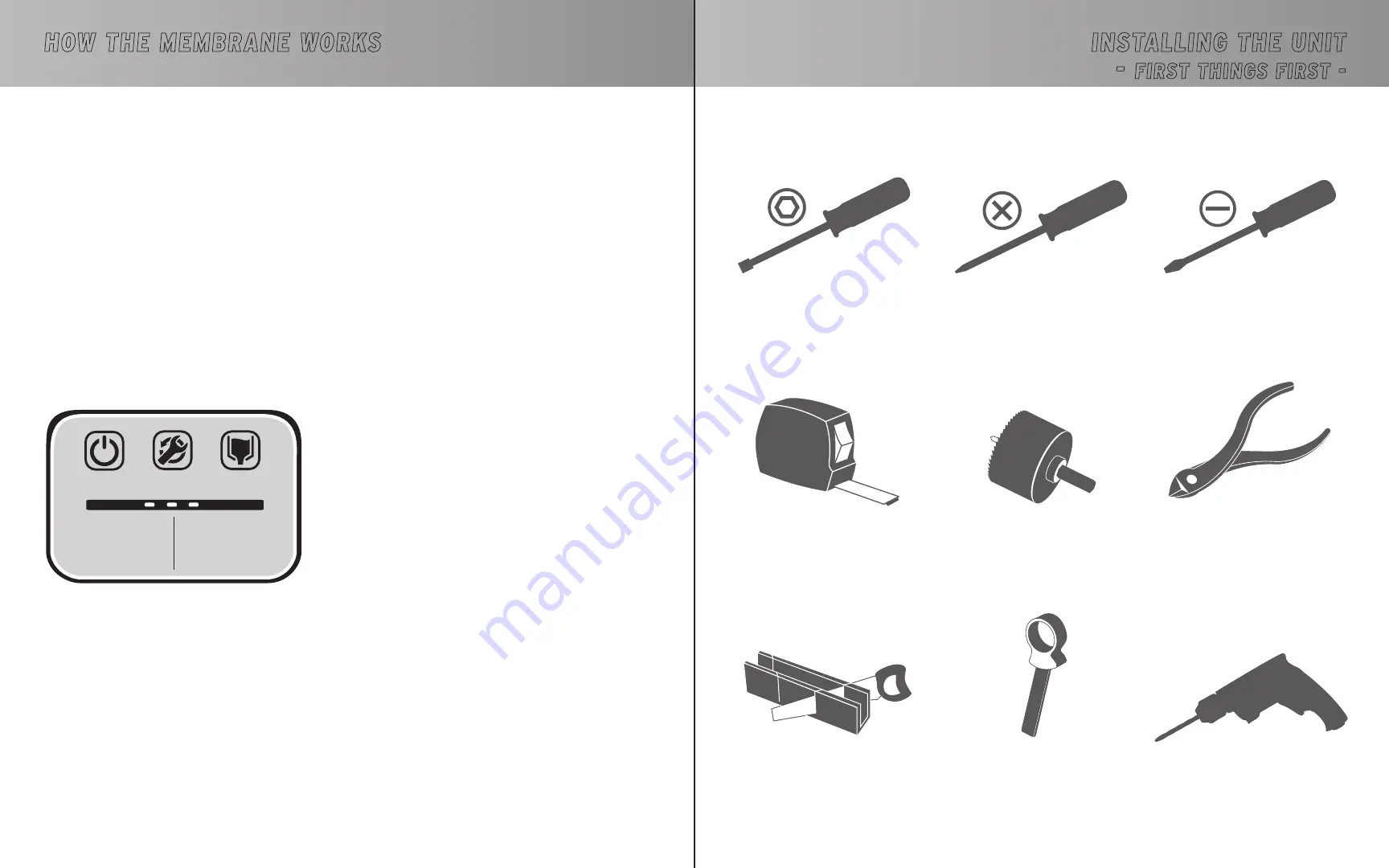
Cutting Pliers

Measuring Tape

Phillips Screwdriver

Hole Saw

2.25” (57 mm)

Drill

0.5” (12.5 mm) bit

Mitre-Box and Saw

PVC Pipe Cutter

2” (50 mm)

Regular Screwdriver

Socket Head Screwdriver

(for the clamps) 

(supplied with the unit)

REQUIRED TOOLS

or

INSTALLING THE UNIT

FIRST THINGS FIRST -

Summary of Contents for AUTOMATIK DF1A160-CB

Page 1: ...OWNER S MANUAL AUTOMATIK SERIES Central Vacuums ...

Page 2: ...suction Lack of air flow will cause the motor to overheat This vacuum cleaner creates suction Keep hair face fingers all body parts and loose clothing away from any openings Never plug in a unit designed to operate with a current of 108V 120V in a 220V 230V outlet and vice versa If the power cord is damaged it must be replaced by a special cord available from the authorized local dealer distributo...

Page 3: ...ATION 20 DV2A32 27 DF2A32 PARALLEL CONFIGURATION 21 DVDC40 DFDC40 SERIES CONFIGURATION 22 DVDC40 DFDC40 PARALLEL CONFIGURATION 23 HOW THE MEMBRANE WORKS 24 INSTALLING THE UNIT FIRST THINGS FIRST 25 27 STEP SEQUENCE 28 34 INSTALLING THE PIPING SYSTEM GENERAL INFORMATION 35 DIFFERENT INSTALLATION POSSIBILITIES RESIDENTIAL AND COMMERCIAL INSTALLATION 36 37 FROM DRY TO WET 38 EXAMPLES OF PROPER AND IM...

Page 4: ...rt begins to be vacuumed and water flows in Water comes into contact with the electrodes The rubber hand opens The rubber hand is closed Step 3 Water flows in reaching the electrodes approx 10 minutes Step 4 The wastewater is evacuated approx 20 seconds To see a video of the sequence go to https www youtube com watch v VEnUJxHEN4M OPERATION SEQUENCE The sensitivity of the electrodes can be modifie...

Page 5: ... of the regular floor brush use a tool specially designed to vacuum liquids If you are using a cleaning kit equipped with jets BEFORE STORING AWAY Cleaning wet surfaces dirties the inside of the hose It is therefore necessary to clean them before storing away the equipment Connect the hose into the wall inlet Keep the unit running for a few minutes as it dries out Optional vacuum toilet paper to a...

Page 6: ... 355 4191 198 68 2 10 8 6 gal 29 L 0 3 gal 1 2 L 15 dia x 49 38cm dia x 122 5cm DF2A311 700 3500 246 62 1 10 0 6 gal 2 3 L DF2A313 2 X 355 4191 198 70 2 10 8 DF2A31 2 x 355 4191 198 70 2 10 8 DF2A32 IN SERIES 4 x 355 6096 198 72 4 2 x 10 8 DF2A32 IN PARALLEL 4 x 355 4191 396 72 4 2 x 10 8 DFDC40 IN SERIES 2 x 395 4799 234 72 2 2 x 7 5 DFDC40 IN PARALLEL 2 x 395 3175 396 72 2 2 x 7 5 DF2A33 4 x 355...

Page 7: ... To remove oversized materials or an accumulation of hair paper etc Strongly suggested when the unit is used by many people commercial applications The decanter configuration is always recommended when enough space is available DECANTER CONFIGURATION Standard head Split head SPLIT HEAD BENEFITS Allows to position the motor in a different room for less noise In case of insufficient space in height ...

Page 8: ... muffler Audioprotek muffler 24V plug 24V plug Cold water supply Cold water supply One motor unit One motor unit Porthole Porthole O ring O ring Porthole window Porthole window Outdoor vent Outdoor vent Dust entry Dust entry Power cord Power cord UNIT DESCRIPTION UNIT DESCRIPTION ...

Page 9: ...ek muffler Audioprotek muffler 24V plug Cold water supply Cold water supply 2 motor unit 1 motor unit Porthole Porthole O ring O ring Porthole window Porthole window Outdoor vent Dust entry Dust entry Rubber hand Rubber hand Power cord Power cord UNIT DESCRIPTION UNIT DESCRIPTION Outdoor vent ...

Page 10: ...g O ring Porthole window Porthole window Porthole window Outdoor vent Dust entry Dust entry Rubber hand Rubber hand Power cord Power cord Power cord Audioprotek muffler Audioprotek muffler Audioprotek muffler Audioprotek muffler Audioprotek muffler UNIT DESCRIPTION UNIT DESCRIPTION DV2A31 27 carries 2 power cord DV2A33 27 carries 2 power cord Outdoor vent Outdoor vent 2 motor unit 2 motor booster ...

Page 11: ...wer cord Power cord Audioprotek muffler Audioprotek muffler Audioprotek muffler Audioprotek muffler Power cord Power cord 24V plug 24V plug UNIT DESCRIPTION DV2A32 27 DF2A32 PARALLEL CONFIGURATION FOR OPTIMUM AIRFLOW DV2A32 27 DF2A32 SERIES CONFIGURATION FOR OPTIMUM SUCTION POWER The DV2A32 27 and DF2A32 can be mounted in two different configurations This one is recommended for optimum suction pow...

Page 12: ...indow Outdoor vent Dust entry Power cord Audioprotek muffler Power cord Rubber hand UNIT DESCRIPTION Vacuum pipe Audioprotek muffler 24V plug One motor booster head 24V plug Cold water supply One motor unit Porthole O ring Porthole window Outdoor vent To outside vent Dust entry Rubber hand Power cord Audioprotek muffler Power cord The DVDC40 and DFDC40 can be mounted in two different configuration...

Page 13: ...triction to the amount of wastewater that can be evacuated the evacuation time could be set on medium On the other hand if the diameter of the pipe leading to the sewer is smaller and restrains the amount of water that can be evacuated increasing the evacuation time to a long flushing time could be necessary ON OFF The first LED will stay lit if the unit is on Press once to turn it off It will the...

Page 14: ... your home includes a septic tank important details are to be considered The unit must be higher than the drain but the motor can be relocated to reduce the noise If the unit is connected directly to the septic tank the decanter option is mandatory INSTALLING THE UNIT FIRST THINGS FIRST GROUND FLOOR BASEMENT SUMP PUMP For compact models the bottom of the P Trap can be installed at 15 38cm from the...

Page 15: ...installing a wooden panel screwed to the wall studs beforehand for more stability Suggested distance from the floor Compact installation 50 125 cm Installation with the decanter Funnel 40 100 cm Unit 65 165 cm Lift the unit and slide its support onto the wall bracket Optimum efficiency Not recommended Each booster head can be installed according to the available space without compromising the heig...

Page 16: ...es to the unit securing it with a clamp N B The tubes have been pre assembled by pressure Do not use glue Connect the suction hose to the unit s dust inlet securing it with a clamp Backflow preventer Optional sold separately Screw the metal hose with the connector Recommended replacing the hose every 10 years POSITIONING THE WATER INJECTORS ON THE DUST INLET Some units are equipped with two water ...

Page 17: ...t the booster head user s guide for more information Parallel configuration Series configuration Steel Muffler STEEL MUFFLER Some units are equipped with a steel muffler to absorb the noise produced by more powerful systems Contrary to plastic mufflers this steel muffler must be installed on the wall You will find the installation method on the sheet provided with the exhaust Back View of the Unit...

Page 18: ...er a carport If your unit includes two motors it is important to use metal piping and couplings for the air outlet To determine where to locate the wall inlets use the length of the vacuum hose as a basis measuring the furthest point from the wall where the wall inlets are to be installed Do the same for all the wall inlets until all areas of the house or building can be reached with the vacuum ho...

Page 19: ...on of the piping towards the unit Inclination INSTALLING THE PIPING SYSTEM DIFFERENT INSTALLATION POSSIBILITIES DIAGRAM OF A COMMERCIAL INSTALLATION Installation example in series In the basement connected under a pipeline under the floor Back to back Always have a slight inclination of the piping towards the unit Under the floor Through the ceiling Inclination Inclination INSTALLING THE PIPING SY...

Page 20: ...ng upwards must be slightly higher than the main pipeline to prevent liquids from flowing back down Figure C If short elbows were used to mount the pipeline these must be taken off The minimum cornering pipe must be at least a medium elbow but a 45o pipe is recommended for all corners for an optimal efficiency The inclination of the main pipeline must tilt a little more than an ordinary vacuum to ...

Page 21: ...41 40 EXAMPLES OF PROPER AND IMPROPER INSTALLATIONS INSTALLING THE PIPING SYSTEM EXAMPLES OF PROPER AND IMPROPER INSTALLATIONS INSTALLING THE PIPING SYSTEM ...

Page 22: ...ch head as illustrated on the following page refer to the diagram of your specific model Connect the unit to the electrical outlet with the power supply cord The vacuum cleaner is now ready to be used EXAMPLES OF PROPER AND IMPROPER INSTALLATIONS 24V wires ELECTRICAL POWER SUPPLY DIAGRAMS OF AN APPROPRIATE CONNECTION 15 amp circuit 108V 120V 16 amp circuit 220V 240V 20 amp circuit 108V 120V 16 amp...

Page 23: ... with a qualified electrician or service person if you are in doubt as to whether the outlet is properly grounded DO NOT MODIFY THE PLUG PROVIDED WITH THE UNITS IF IT DOES NOT FIT THE OUTLET HAVE A PROPER OUTLET INSTALLED BY A QUALIFIED ELECTRICIAN These units are for use on a nominal 108V 120V or 220V 240V circuit and has a grounding attachment plug that looks like the one illustrated below Make ...

Page 24: ...uires a minimum maintenance and your system is no exception to the rule We therefore recommend that you inspect your motor brushes after 500 hours of use to check how worn they are and replace them if need be On average this inspection should occur once every 3 to 5 years for residential applications and once or twice a year for commercial applications When the time comes contact your retailer or ...

Page 25: ...either cut or disconnected from one of the wall inlets If the unit won t start up after these steps the printed circuit is defective THE UNIT WON T SHUT DOWN SOLUTION Check the 24V circuit as follows Disconnect one of the two wires on the unit s 24V circuit If the unit shuts down the problem could be that two 24V wires are touching themselves somewhere or that the wall inlet is defective If the un...

Page 26: ...FLOW CONSTANT CONFIGURATION PAR DÉFAUT POUR LE COMMERCIAL ÉCOULEMENT D EAU CONTINUE INTERMITTENT CONFIGURATION PAR DÉFAUT POUR LE RÉSIDENTIEL ÉCOULEMENT D EAU PAR INTERMITTENCE ANNEXE I CIRC14R5NA1 CIRC14R5NA2 CIRC14R5INT DIAGRAMME DE CONNEXION 4 gal 18 L DV1A150 DV1A160 CB DF1A150 DF1A160 CB ANNEX I CIRC14R5NA1 CIRC14R5NA2 CIRC14R5INT Connection diagram 4 gal 18 L DV1A150 DV1A160 CB DF1A150 DF1A1...

Page 27: ...LIVR 09 PRINTED IN CANADA 07 18 Central Vacuums ...

Reviews: