background image

26

27

•  G2-2X5-M : 15 amp./208V - 240V
•  G2E-2X5-M : 20 amp./208V - 240V

GROUNDING INSTRUCTIONS

These units must be grounded. If it should malfunction or breakdown, grounding 
provides a path of least resistance for electric current to reduce the risk of electric 
shock. This appliance is equipped with a cord having an equipment-grounding 
conductor and grounding plug. The plug must be inserted into an appropriate 
outlet that is properly installed and grounded in accordance with all local codes 
and ordinances.

WARNING 

- Improper connection of the equipment-grounding conductor can result in 

a risk of electric shock. Check with a qualified electrician or service person if you are in 
doubt as to whether the outlet is properly grounded. 

DO NOT MODIFY THE PLUG PROVIDED WITH THE UNITS -  

IF IT DOES NOT FIT THE OUTLET, HAVE A PROPER OUTLET INSTALLED  

BY A QUALIFIED ELECTRICIAN.

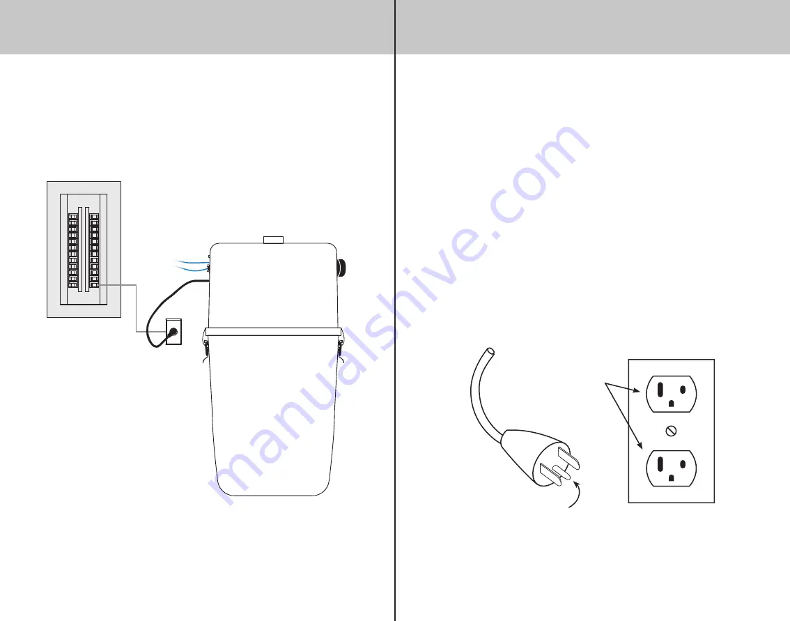
These units are for use on a nominal 120V or a 230V circuit and have a grounding 
attachment plug that looks like the one illustrated below. Make sure that the electrical 
cord is connected to an outlet having the same configuration as the plug.

NO ADAPTOR SHOULD BE USED WITH THIS APPLIANCE.

Grounded

Outlet

Grounded pin

*Illustration of a north-americain electrical outlet

If you experience voltage surge problems on your electrical circuit in spite of 
adequate connections, a high magnetic circuit breaker can be installed on your 
electrical panel. Contact an electrician for more information.

DIAGRAM OF AN APPROPRIATE CONNECTION

Electrical panel

All units used in North America has a

 circuit of 15 amp./120V, 

whereas the International 

has a 

circuit of 10 amp./230V 

except for some exceptions :

The electric installation must be 
compliant to the building code in 
effect of your state or country.

ELECTRICAL POWER SUPPLY

ELECTRICAL POWER SUPPLY

Summary of Contents for COMPACT Series

Page 1: ...MAN COMP BI PRINTED IN CANADA 02 21 OWNER S MANUAL COMPACT SERIES Cleaning Systems ...

Page 2: ... and anything that may reduce airflow suction Lack of air flow will cause the motor to overheat This vacuum cleaner creates suction Keep hair face fingers all body parts and loose clothing away from any openings Never operate without dust bag and or filter in place Never plug in a unit designed to operate with a current of 120V in a 230V outlet and vice versa If the power cord is damaged it must b...

Page 3: ...rainvac product It is a sound investment that will satisfy your vacuuming needs for years to come Drainvac s central vacuum cleaners are manufactured and checked at our factory by our qualified staff who have been specifically trained to this end A number of installations and operating methods must be followed to ensure your system s maximum performance and to avoid unnecessary service calls Pleas...

Page 4: ...RNATIONAL 220V 240V TECHNICAL SPECIFICATIONS PRO SERIES NORTH AMERICA 108V 120V MODELS AIR WATTS H2O CFM DECIBELS AMPS GAL L SIZE in cm PRO106 600 100 154 69 12 75 3 75 17 12 dia x 23 30 dia x 58 MODELS AIR WATTS mmH2O m3 h DECIBELS AMPS GAL L SIZE in cm PROE107 700 3880 315 65 7 3 75 17 12 dia x 23 30 dia x 58 INTERNATIONAL 220V 240V You have purchased one of the following models Identify the one...

Page 5: ...m3 h DECIBELS AMPS GAL L SIZE in cm G2E 007 700 3880 315 58 7 9 41 15 dia x 28 38 dia x 70 G2E 007i M 700 3500 246 62 7 4 G2E 2X5 M 2 x 520 4318 271 72 14 INTERNATIONAL 220V 240V G2 2X3 M G2 2X5 M and G2E 2X5 M include 2 motors TECHNICAL SPECIFICATIONS UNIT DESCRIPTION ILLUSTRATED CONFIGURATION OF A SINGLE MOTOR UNIT Pro series S1000 series and models G2 008 G2E 007 Your model may vary from the il...

Page 6: ...re différente Veuillez préalablement vérifier la configuration de votre modèle Se référer au verso Different models of the same product line can have different dust outlet configurations Please check your model s configuration beforehand refer to back Purvac STANDARD DE LUXE EXTRA POUR LES GAMMES FOR PRODUCT LINES 41 L 9 gal POUR LES CUVES DE FOR CANISTERS OF Les 3 plis offrent une filtration de h...

Page 7: ...NSTALL THE UNIT We recommend installing the system on the lowest level of the building to avoid having to work against gravity Dust and solids will fall easier than being pulled upwards this is why the basement is generally the most ideal location If there is no basement the garage or a storage room will do MINIMUM DIMENSIONS AND SPACING Itisimportanttoinstalltheunitinalocationwhereitwillbeeasilya...

Page 8: ...rews in the middle area only If the wall is covered with gypsum board we recommend installing a wooden panel screwed to the wall studs beforehand for more stability Then screw the bracket to the wall with the five 5 screws supplied with the unit UNIT INSTALLATION 2 CONNECTING THE DUST INLET Connect the dust inlet onto the unit securing it with a collar do not glue Lift the head to slide its suppor...

Page 9: ...preinstalled to the unit 4 DUST BAG Install the appropriate dust bag for your model and follow the instructions printed on the back of the packaging Spacing In contact UNIT INSTALLATION 5 AUDIOPROTEK MUFFLER TWO MOTOR SERIES ONLY Units including a two motor system such as G2 2X3 M G2 2X5 M G2E 2X5 M are supplied with audioprotek mufflers Peel the plastic strip from the foam and stick the muffler o...

Page 10: ...evacuated air does not lead under a carport If your unit includes two motors it is important to use metal piping and couplings for the air outlet To determine where to locate the wall inlets use the length of the vacuum hose as a basis measuring the furthest point from the wall where the wall inlets are to be installed Do the same for all the wall inlets until all areas of the house or building ca...

Page 11: ...LATION Main pipeline Exhaust pipeline Wallyflex Installation Retraflex Installation Vroom Retract Vac Installation In the basement connected under a pipeline under the floor Back to back On the first floor connected above a pipeline under the floor On the top floor at the end of a pipeline On an intermediary floor ...

Page 12: ...PER AND IMPROPER INSTALLATIONS PIPING INSTALLATION Joint with inside stoppers Thin wall Thick wall For wall plates only Smooth joint without inside stoppers EXAMPLES OF PROPER AND IMPROPER INSTALLATIONS PIPING INSTALLATION ...

Page 13: ...must be installed near the unit We strongly recommend installing an electrical circuit which will be used only for the unit Install the 24 volt wires from the network each wall inlet to the unit Connect the unit to the electrical outlet with the power supply cord The unit is now ready to be used EXAMPLES OF PROPER AND IMPROPER INSTALLATIONS PIPING INSTALLATION ELECTRICAL POWER SUPPLY ...

Page 14: ...ET HAVE A PROPER OUTLET INSTALLED BY A QUALIFIED ELECTRICIAN These units are for use on a nominal 120V or a 230V circuit and have a grounding attachment plug that looks like the one illustrated below Make sure that the electrical cord is connected to an outlet having the same configuration as the plug NO ADAPTOR SHOULD BE USED WITH THIS APPLIANCE Grounded Outlet Grounded pin Illustration of a nort...

Page 15: ... they are and have them replaced if necessary On average this inspection should occur once every 3 to 5 years When the time comes contact your retailer or distributor for this maintenance procedure Take note that the motor brushes are not included in the warranty FILTER AND DUST BAG You must clean the filter and replace the dust bag periodically This will prevent your vacuum from losing any power ...

Page 16: ...ted from one of the wall inlets or the hose is defective If the unit does not start up after all theses steps the printed circuit is defective THE UNIT WON T SHUT DOWN SOLUTION Check the 24 volt circuit as follows Disconnect one of the two wires on the unit s 24 volt circuit If the unit shuts down the problem could be that two 24 volt wires are touching themselves somewhere or that the wall inlet ...

Page 17: ...ETE27 LED CONTACT 24 VOLTS SWITCH ON OFF INTERRUPTEUR SWITCH ON OFF INTERRUPTEUR 0 1 8 6 4 2 RELA 02 120V TIMER M1 M2 RESET 15A RESET 15A ANNEXE II CIRC03 DIAGRAMME DE CONNEXIONS 2 MOTEURS 110 120 VOLTS G2 2X3 M ANNEX II CIRC03 CONNECTION DIAGRAM 2 MOTORS 110 120 VOLTS G2 2X3 M 120V 24V 24V COM 120V LED CONTACT 24 VOLTS SWITCH ON OFF INTERRUPTEUR SWITCH ON OFF INTERRUPTEUR TIMER M2 M1 TETE06 FUSE ...

Page 18: ...2X5 M G2E 25 M ANNEXE IV CIRC19 DIAGRAMME DE CONNEXIONS 1 MOTEUR 220 240 VOLTS PROE107 ANNEX IV CIRC19 CONNECTION DIAGRAM 1 MOTOR 220 240 VOLTS PROE107 GROUND TRAY GREEN WIRE MISE À LA TERRE PLATEAU FIL VERT GROUND TRAY GREEN WIRE MISE À LA TERRE PLATEAU FIL VERT 1 MOTOR MOTEUR N 1 MOTOR MOTEUR L NEUTRAL BLUE WIRE NEUTRE FIL BLEU LINE IN BROWN WIRE ALIMENTATION ENTRÉE FIL BRUN 220 240 VOLTS P1 P3 ...

Reviews: