background image

115 VAC, 60Hz

30 WATTS

IN

OUT

FUSE

1 / 2 A, 250 V

SLO - BLO

CAUTION:

ATTENTION:

                           - RISK
OF FIRE - REPLACE
FUSE AS MARKED
AFTER DISCONNECTING
UNIT FROM AC LINE.

- RISQUE D'INCENDIE -
REMPLACEZ FUSIBLE DU
TYPE INDIQUE APRES
DEBRANCHER DU SECTEUR.

IF

LOOP

RF

INPUT

COMPOSITE IF

RF

OUTPUT

SERIAL #

®

MADE IN THE U.S.A. BY

Installation     5

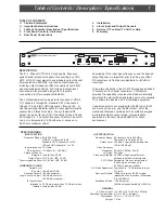
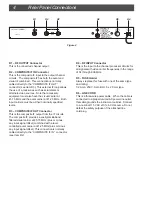
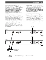
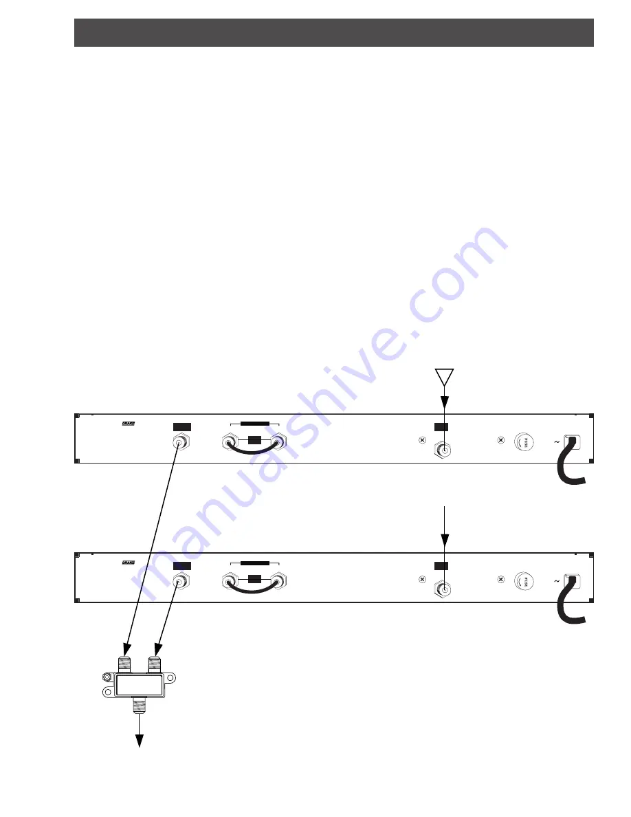
CONNECTIONS AND CONTROLS – All
connections to and from the HCP1550 are made
through the rear panel.  Figure 3 shows a typical two
channel processing installation involving the
converting of an off-air signal and a CATV signal.
Additional channels can be processed by using
additional channel processor units and either
multi-port combiners or combinations of two-port
combiners.

INSTALLATION NOTES – Level adjustment
provides optimum performance in multichannel
installations.  The channel processor outputs should
be checked periodically with a spectrum analyzer to
maintain a ±1 dB variation of adjacent channel
carriers.  Aural/Visual (A/V) ratios should be held to
–15 dB or less.  The ‘Output Level’ and ‘A/V Ratio’
controls are used respectively to make these
adjustments.  If an output level of less than
+50 dBmV is required, add an attenuator of the
appropriate value to the modulator output.
Example:  For an output level of +45 dBmV, add a
12 dB attenuator pad to the modulator output and set
the output level.

RACK MOUNTING – Adequate ventilation is very
important in multichannel installations.  Units should
be spaced apart by at least one panel height
wherever possible, and some air movement is
advisable in enclosed rack cabinets.  Excessive heat
will shorten component life and unit performance will
be degraded without proper cooling.

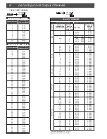
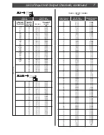
FCC PAR.76.612 – Certain cable channel
frequencies assigned to aviation and navigation
communications require frequency offsets.  The
OUTPUT CHANNEL switches set the output
frequency for a visual carrier frequency of ‘xx.25’ or
‘xxx.25’ MHz only.  The exact output frequency,
however, is relative to the input signal frequency and
any additional offset (plus or minus) set by the
OFFSET switches.  Refer to the ‘Output Channel’ list
in the Installation section of this manual to determine
the required offset for a particular output channel.

Figure 3 - Typical Multiple Channel Processor Installation.

OUT

5-1000 MHz  -130 dB RFI

OUT

3611

2-WA

Y  SPLITTER

IN

2-WAY SPLITTER/

COMBINER

RF OUT

TO SYSTEM

HCP1550

HCP1550

OFF-AIR

CATV

Summary of Contents for DRMM4

Page 1: ...uction Manual HCP1550 Commercial Heterodyne Channel Processor For use in NTSC systems is a registered trademark of the R L Drake Company Copyright 2004 R L Drake Co P N 3852453K 09 2004 Printed in the U S A ...

Page 2: ...ular attention to cords at plugs convenience receptacles and the point where they exit from the product 14 Outdoor Antenna Grounding If an outside antenna or cable system is connected to the product be sure the antenna or cable system is grounded so as to provide some protection against voltage surges and built up static charges Article 810 of the National Electrical Code ANSI NFPA 70 provides inf...

Page 3: ...put the IF Loop out and Loop in and the RF Output All of the mentioned features combined with a carefully designed low intermodulation output stage provide reliable operation in a densely crowded SMATV or cable environment TABLE OF CONTENTS ii Caution Statements ii Important Safety Instructions 1 Table of Contents Description Specifications 2 Front Panel Controls Indicators 4 Rear Panel Connection...

Page 4: ...hrough 125 STANDARD CATV CHANNEL 125 CATV CATV OFF AIR IRC HRC STD INPUT CHANNEL 100 RF INPUT 2 5 CHANNEL PLAN Figure 1 F1 F2 F3 F4 F5 F6 F7 F8 F9 F3 INPUT CHANNEL Number Switch Sets the input channel number for Off Air TV channels 02 through 69 for standard CATV channels 02 through 125 or IRC HRC channels 01 through 125 See also Item F2 which sets the type of channel Off Air or various types of C...

Page 5: ...iply the thumbwheel switch number times 6 25 kHz to determine the offset For example a setting of 2 sets a 2 x 6 25 kHz 12 5 kHz offset Remember to also set the direction of any offset plus or minus as required Certain CATV channels require aviation or navigation offsets Several examples follow F7 OUTPUT CHANNEL Number Switch Sets the output channel number for standard CATV channels 02 through 78 ...

Page 6: ...d the aural carrier at 41 25 MHz Both input carriers must be at their nominally specified levels R3 COMPOSITE IF OUT Connector This is the composite IF output from the IF circuits The composite IF provides a vestigial sideband filtered visual carrier at 45 75 MHz plus or minus any input signal offset combined with a level controlled aural carrier at 41 25 MHz plus or minus any input signal offset ...

Page 7: ...riers Aural Visual A V ratios should be held to 15 dB or less The Output Level and A V Ratio controls are used respectively to make these adjustments If an output level of less than 50 dBmV is required add an attenuator of the appropriate value to the modulator output Example For an output level of 45 dBmV add a 12 dB attenuator pad to the modulator output and set the output level RACK MOUNTING Ad...

Page 8: ...0 168 00 174 00 180 00 186 00 192 00 198 00 204 00 210 00 216 00 222 00 228 00 234 00 240 00 246 00 252 00 258 00 264 00 270 00 276 00 282 00 288 00 294 00 300 00 306 00 312 00 318 00 324 00 330 00 336 00 342 00 348 00 354 00 360 00 366 00 372 00 378 00 384 00 390 00 396 00 402 00 408 00 414 00 420 00 426 00 EIA NCTA Numeric Equivalent InputChannel 2 3 4 1 5 6 95 96 97 98 99 14 15 16 17 18 19 20 2...

Page 9: ...1 42 43 44 45 46 47 48 49 50 51 52 53 54 55 56 57 58 59 60 61 62 63 64 65 66 67 68 69 70 71 72 73 74 75 76 77 78 95 96 97 98 99 Visual Carrier Frequency MHz 55 25 61 25 67 25 77 25 83 25 175 25 181 25 187 25 193 25 199 25 205 25 211 25 121 25 127 25 133 25 139 25 145 25 151 25 157 25 163 25 169 25 217 25 223 25 229 25 235 25 241 25 247 25 253 25 259 25 265 25 271 25 277 25 283 25 289 25 295 25 301...

Page 10: ...orking days after it arrives at R L DRAKE if we have all the facts If we must call you it may take longer R L DRAKE is not responsible for damage caused by lightning nonprofes sional alterations acts of God shipping damage poor storage handling etc R L DRAKE will make note of any shipping damage upon receipt You will need to send proof of purchase to receive warranty service Typically a copy of th...

Page 11: ...rtant to obtain proper performance from this product Therefore carefully read the Instruction Manual This warranty does not apply to any defect that R L DRAKE COMPANY determines is due to 1 Improper maintenance or repair including the installation of parts or accessories that do not conform to the quality and specifications of the original parts 2 Misuse abuse neglect or improper installation 3 Ac...

Page 12: ...R L Drake Company 230 Industrial Drive Franklin Ohio 45005 U S A Customer Service and Parts Telephone 1 937 746 6990 Telefax 1 937 743 4576 World Wide Web Site http www rldrake com ...

Reviews: