0.000 Mbits/S
QAM OUTPUT
MEQ1000A MULTIPLEXING HYBRID QAM MODULATOR
Installation & Mounting / Front Panel Controls
7
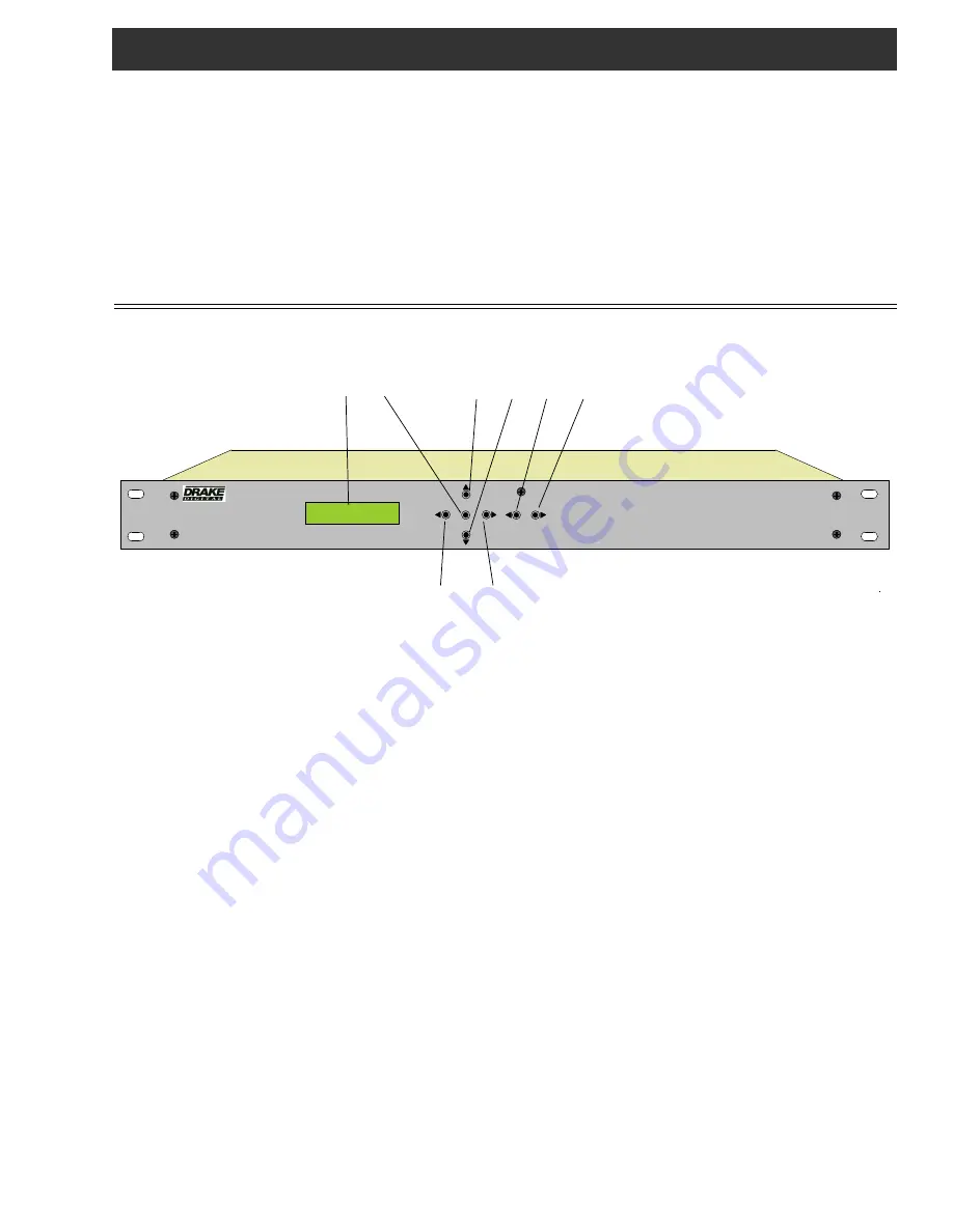
F1 F2 F5 F6 F7 F8
F3 F4
F1, LCD Display –
This display presents the selected
menu screen and the parameter settings. The backlight in
the display is on when power is applied.
During operation, the S/N (signal to noise ratios) of the
demodulator input signals are displayed. For 8VSB inputs,
the threshold is about 15 dB. For QAM inputs, the thresh-
old is about 23 dB for 64QAM and 27 dB for 256QAM. You
should maintain a S/N several dB above these thresholds for
reliable operation.
F2, ENTER Button –
Use the ENTER button to enter the
adjust mode or to save and load a new setting or settings
after adjustment. Hold for 2 seconds until the bottom line of
the display starts to flash to enter the adjust mode. After
entering the adjust mode, momentarily pressing the ENTER
button again will load and save any settings that may have
been changed using the F5 & F6 buttons.
F3 & F4, ◄ (Left) and ► (Right) Buttons –
Use the left
and right arrow buttons to navigate from screen to screen
to view a parameter setting. These buttons are operational
in the view mode or the adjust mode. Using only these
buttons will not change any parameter settings. After a
short period of button inactivity, the default display will
be returned.
F5 & F6
, ▲ (U
p
)
a
nd ▼ (D
own
)
Buttons –
Use the down
and up arrow buttons to change the value of a viewed
parameter setting. The unit must be in the adjust mode with
the display flashing in order for these buttons to become
active for changing a parameter setting. If the unit is not in
the adjust mode, pressing the up button will display the
firmware version number or pressing the down button will
display the output QAM symbol rate.
F7 & F8
, ◄ Se
l
ect ►
Buttons -
Use the left or right
Select arrow buttons to select which section of the unit to
control. Select one of the input modules or the QAM
modulator / up converter section.
INSTALLATION AND MOUNTING NOTES
This equipment is designed to be installed in a standard 19” rack. A built in fan provides air movement through the unit.
When connecting an incoming RF signal source to two DTD1000 modules, note that the antenna or CATV source must be con-
nected to both the A and B input connectors. These inputs are kept separate in case the inputs need to come from different
antennas or one antenna and one CATV source.
Connect the AC line cord to an appropriate source of 120 volt, 50/60 Hz AC power. The MEQ1000A is always on once the AC
power cord is connected to its power source.
ENTER
SELECT


