A / V
RATIO
AUDIO
LEVEL
AUDIO
OVER DEV
VIDEO
LEVEL
RF OUT
LEVEL
OUTPUT
TEST
VIDEO
OVER MOD
CHANNEL
CH
IRC
HRC
STD
ANT /
CATV
SEL
F8- ANT/CATV
Press to switch between the CATV or ANT (off-air
channels) output.
F9 - SEL (select)
When set to the CATV channel frequency plan, use
button F9 to further select the type of system channel map
that is required. Select among STD, HRC, or IRC. The
indicators, F7, will display the selected setting.
F10, F11 - CHannel Select Buttons
Press F10 to decrement the selected channel settings.
Press F11 to advance to the next highest numbered
channel.
F12 - RF OUTPUT LEVEL
This screwdriver adjustment permits decreasing the RF
output level a minimum of 10 dB below its specified
output level as the control is rotated counterclockwise.
The maximum output level of +55 dBmV is set with the
adjustment approximately fully clockwise.
NOTE: If an output level of less than +45 dBmV is
required, add an attenuator of the appropriate value at
the modulator output and operate the modulator at the
highest practical level (not exceeding 55 dBmV).
Example: For an output level of +35 dBmV, add a 12 dB
or 18 dB attenuator pad to the modulator output and set
the output level.
F13- OUTPUT
This type "F" connector provides a test monitor output that
is nominally 30 dB below the main rear panel RF output
level.
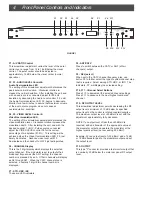
F1 F2 F3 F4 F5 F6 F7 F8 F11
FIGURE 1
F1 - A/V RATIO Control
This screwdriver adjustment varies the level of the aural
carrier over a range from 12 to 18 dB below the visual
carrier. The aural carrier should be adjusted to
approximately 15 dB below the visual carrier (normal
operation).
F2, F3 - AUDIO LEVEL Control &
Audio Overmodulation LED
The setting of this screwdriver adjustment determines the
peak aural carrier deviation. Clockwise rotation in-
creases the carrier deviation. After installing the unit, and
with an audio source connected, adjust for 25 kHz
deviation by advancing the Audio Level control, F2, until
the Audio Overmodulation LED, F3, begins to illuminate.
Monitor for a few minutes to assure that maximum volume
of the audio source program does not cause an
overmodulation condition.
F4, F5 - VIDEO LEVEL Control &
Video Overmodulation LED
The setting of this screwdriver adjustment determines the
video modulation level. Clockwise rotation increases the
modulation depth. After installing the unit, and with the
desired nominal 1 Volt P-P video source connected,
adjust the VIDEO LEVEL control F4 for the correct
percentage of modulation (87.5%). This setting will be
achieved when the Video Overmodulation LED, F5, just
barely illuminates. Advance video level until F5
illuminates and then back off until F5 just extinguishes.
F6 - CHANNEL Display
This is the 3 digit display which displays the selected
output channel. If the modulator is set to output off-air
broadcast frequencies (the ANT setting) the channel
number is preceded by an A. Off-air channels will display
as A2 through A27. When the CATV channel plan is
selected, a numeric 3 digit EIA channel number is
displayed.
F7 - STD, HRC, IRC
These are LED indicators.
F9 F10 F12 F13
4 Front Panel Controls and Indicators


