background image

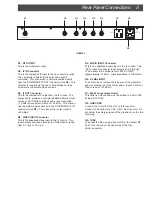
Rear Panel Connections     5

RF OUTPUT

MADE IN TAIWAN

IF IN

IF OUT

VIDEO INPUT

AUDIO INPUT

4.5 MHz INPUT

120V AC
60 Hz  618W

600W MAX

R1 - RF OUTPUT
This is the modulator output.

R2 - IF IN Connector
This is the composite IF input to the up converter circuits.
The composite IF has both the aural and visual IF
combined.  This connection is normally cabled directly
from the “COMPOSITE IF OUT” connector (See R3).  This
external IF loop allows the use of accessories such as
scramblers or alternate video sources.

R3 - IF OUT Connector
This is the composite IF output from the IF circuits.  The
composite IF provides a vestigial sideband filtered visual
carrier at 45.75 MHz combined with a level controlled
(-15 dBc typical) aural carrier at 41.25 MHz.  This connec-
tion is normally cabled directly to the “COMPOSITE IF IN”
connector (See R2).  The video carrier output level is
+40 dBmV.

R4 - VIDEO INPUT Connector
This is the baseband video input to the IF circuits.  This
input accepts baseband through 4.2 MHz video at levels
from 0.7 Vp-p to 1.5 Vp-p.

R5 - AUDIO INPUT Connector
This is an unbalanced audio input to the IF circuits.  This
“RCA” (phono) connector input accepts 40 Hz through
15 kHz audio at a nominal level of 250 mV RMS
(approximately -10 dBu).  Input impedance is 10K Ohms.

R6 - 4.5 MHz INPUT
To use this input, remove the top cover of the modulator
and move jumper J2 to the ON position.  Input 4.5 MHz at
R6 at a level of +37 dBmV.

R7 - 600 W Convenience Outlet
This outlet is unfused and must be limited to a 5A or 600
W load at 120 VAC.

R8 - LINE CORD
Connect the 3 wire IEC line cord to this connector.
Connect to a nominal 115 VAC ±10%, 60 Hz source.  Do
not defeat the safety purpose of the ground pin on the line
cord plug.

R9 - FUSE
To access the fuse, unplug line cord from the socket R8.
Pull out on the tab on the upper side of the fuse
holder assembly.

          R1                                                                   R2                R3          R4           R5          R6                       R7                 R8

FIGURE 2

    R9

Summary of Contents for VM2551

Page 1: ...Instruction Manual is a registered trademark of the R L Drake Company Copyright 2005 R L Drake Company P N 3852551B 12 2005 VM2551 Commercial Video Modulator For use in NTSC systems...

Page 2: ...y purpose of the polarized plug Alternate Warnings If this product is equipped with a three wire grounding type plug a plug having a third grounding pin the plug will only fit into a grounding type po...

Page 3: ...can can be inserted via the rear panel 4 5 MHz input These features combined with a carefully designed low intermodulation output stage provide reliable operation in a densely crowded SMATV or cable e...

Page 4: ...range from 12 to 18 dB below the visual carrier The aural carrier should be adjusted to approximately 15 dB below the visual carrier normal operation F2 F3 AUDIO LEVEL Control Audio Overmodulation LE...

Page 5: ...rrier output level is 40 dBmV R4 VIDEO INPUT Connector This is the baseband video input to the IF circuits This input accepts baseband through 4 2 MHz video at levels from 0 7 Vp p to 1 5 Vp p R5 AUDI...

Page 6: ...switch SW2 Set switch SW2 to the Pre emphasis OFF position The factory default setting is Pre emphasis ON for mono operation CONNECTIONS AND CONTROLS All connections to and from the VM2551 are made th...

Page 7: ...ance Pre emphasis Frequency Response Total Harmonic Distortion Hum and Noise 4 5 MHz INPUT Internal Jumper Change to Activate Input Level COMPOSITEIF LOOP IF Frequency Loop Level Loop Impedance GENERA...

Page 8: ...be on file at R L DRAKE you will need to send proof of purchase to receive warranty service Typically a copy of the invoice from an R L DRAKE dealer will suffice The warranty is for the original owner...

Page 9: ...enance repair anduseareimportanttoobtainproperperformancefromthisproduct Thereforecarefully readtheInstructionManual ThiswarrantydoesnotapplytoanydefectthatR L DRAKECOMPANYdeterminesisdue to 1 Imprope...

Page 10: ...R L Drake Company 230 Industrial Drive Franklin Ohio 45005 U S A Customer Service and Parts Telephone 1 937 746 6990 Telefax 1 937 806 1576 World Wide Web Site http www rldrake com...

Reviews: