background image

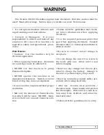
The Dramm CD100 Chemdose applies toxic chemicals.  Extreme caution must be

used!  Read all warnings.  Serious injury or death can occur from misuse.

WARNING

Chemdose Manual

5

• Do not operate machine without read-
ing all warnings and instructions.

• Owners  or  Managers:    It  is  your
responsibility to inform and instruct any
employee  who  uses  this  machine  in
regards to safety and operational   proce-
dures.

W

HEN

S

PRAYING

:

•  Caution:    Use  this  machine  only  for
chemical application.

• When  applying  hazardous  chemicals
care and logic must be adhered to.

•  NEVER  use  this  machine  to  pump
Flammable liquids.

•  NEVER  operate  this  machine  in  an
explosive environment.   Switch or motor
brush arcing may cause an explosion.

• Do not use this machine without proper
ventilation.

• Mix only the amount of chemical solu-
tion which will be used.   NEVER - Keep,
store or hold over unused chemical solu-
tion.

• Follow all E.P.A. guidelines and chemi-
cal  label  information  when  applying
chemicals.

•  Use  the  re q u i red  personal  pro t e c t i o n
gear  when  applying  chemicals.    Consult
chemical label or chemical manufacturer
when in doubt.

•  Be  sure  to  connect  correct  voltage  to
receptacle.

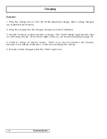
• Do not charge the unit if it is warm to
the  touch  after  use.    Allow  unit  to  cool
before charging.

• Never use any charger but the one pro-
vided  to  charge  the  battery,  damage  to
the unit or personal injury may result.

• Exercise normally accepted safety pro-
cedures when using electricity.

•  After  use  -  Double  rinse  pesticide  /
chemical tank.  Clean nozzle and suction
line thoroughly.  Store unit in a safe loca-
tion  away  from  children  and  unautho-
rized personnel.

• Follow all E.P.A. guidelines for re-entry.

Summary of Contents for CHEMDOSE CD-100

Page 1: ...CHEMDOSE Owners Manual CD 120...

Page 2: ...Mixing 8 Operation 9 Charging 10 MS 20E Sprayer Cart Bottom Draw Instructions 11 MS 20E Sprayer Cart Tank Assembly Diagram Parts List 12 Chemdose Assembly Diagram Parts List 13 Chemdose Pump Assembly...

Page 3: ...machine without proper ventilation Mix only the amount of chemical solu tion which will be used NEVER Keep store or hold over unused chemical solu tion Follow all E P A guidelines and chemi cal label...

Page 4: ...changing the preci sion of each dose A cycle counter is located on the control face of the Chemdose to help with counting The Chemdose cart and tank are designed to fit down standard green house aisle...

Page 5: ...ach button separately to ensure proper opera tion of both Make sure that nothing is blocking the output Proper flow should be an even aerated flow E Uncoil the hose and make sure that there are no kin...

Page 6: ...ount of product per 100 gallons 1 2 3 4 5 6 7 8 9 10 11 12 amount to mix in 20 gallons 0 2 0 4 0 6 0 8 1 0 1 2 1 4 1 6 1 8 2 0 2 2 2 4 amount of product per 100 gallons 13 14 15 16 17 18 19 20 21 22 2...

Page 7: ...osing 5 Keep track of the number of shots per full charge After 16 000 shots the volume will decrease from the pump even though the machine will appear to dose correctly 6 After application thoroughly...

Page 8: ...eptacle on the Chemdose 3 Switch the three position switch to charge The Fast Charge light should come on indicating charge If the Fault light comes on see trouble shooting on page 16 4 Allow to charg...

Page 9: ...ter street elbow and hose barb fitting together Then screw the assembly into the tank 4 With the tank in the cart with the outlet to the rear and the Chemdose in place measure the red suction hose fro...

Page 10: ...2 DII096 Handle Assembly 1 3 DIII20A MSO Pump Bracket 1 4 DIII21 Side Leg 2 5 DIII59 Chemdose Bracket 1 6 DI0563 Chemdose Box 1 7 1899041 6 Caster 2 8 SNI0275 OP 5 8 10 X 2 Wheel 2 9 SP0020 LC 20 Gal...

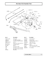
Page 11: ...1 One Shot Timer 90 0003 Switch A3M Plug 3 pin male C3F Receptacle 3 pin female C4F Receptacle 4 pin female D10563 Steel Box D10624 Bench Wand D10625 Floor Wand D10626 Hanging Basket Wand D10633A Grip...

Page 12: ...94 236 11 94 231 05 94 230 05 94 237 05 94 231 30 94 232 05 94 238 03 11 111 00 Complete Pump Head Upper Housing Switch assembly Switch kit Check Valve Kit Upper Housing Kit Valve Kit Diaphragm Drive...

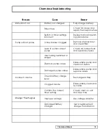
Page 13: ...bris in pump valves Disassemble pump and clean out debris Check all connections and repair any leaks Damaged pump valves Disassemble pump and replace valves Clogged nozzle Disassemble clean and re ins...

Reviews: