background image

15

10.  OPERATING INSTRUCTIONS FOR 17684/17685.

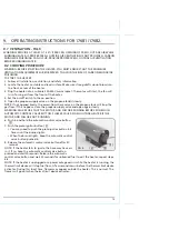
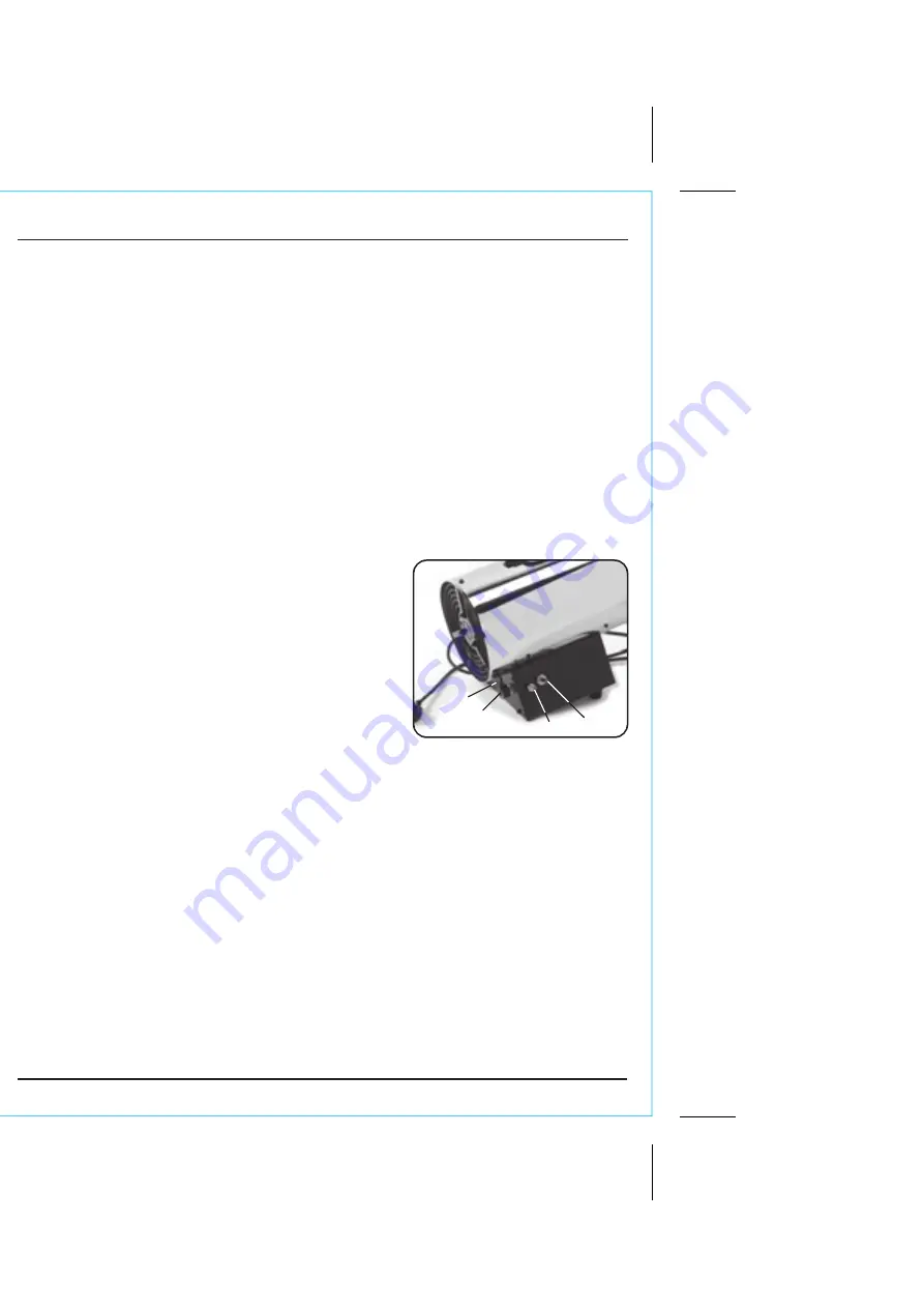
10.1  IGNITION SYSTEM - FIG. 6

Ignition is automatic with this heater as soon as the gas valve button is depressed, with a 
continuous spark from the spark plug igniting the gas. As the thermocouple heats up, a low 
voltage is fed to the Flame Failure valve, causing the valve to open, so that after a few 
seconds, the gas valve button may be released and the flame is established.

10.2  SAFETY CONTROL SYSTEM

Should the flame extinguish for any reason, the thermocouple will quickly cool, causing the 
Flame Failure valve to close, shutting off the gas supply. Similarly, should there be a power 
failure, causing the fan motor to stop, the Safety Shut-Off valve solenoid will become 
de-energised, and therefore shut off the gas supply.

Additionally, the machine is equipped with thermal overload protection, which will 
intervene should the/unit overheat shutting off the electrical supply.

10.3  STARTING PROCEDURE

WARNING: BEFORE STARTING THE HEATER, YOU MUST ENSURE THAT THE MINIMUM 
VENTILATION REQUIREMENTS ARE OBSERVED TO AVOID THE RISK OF CARBON MONOXIDE 
POISONING.
1.  Ensure there is sufficient gas and that it is correctly connected.

2.  Open the supply valve on the gas cylinder, and fully 

open the regulator valve adjacent to the gas inlet pipe.

3.  Plug the heater in to a suitable power supply.
4.  Set the flame intensity control valve 

, to a low 

setting.

5.  Set the fan switch 

 to the ON (I) position. Confirm 

the fan operates.

6.  Hold in the gas valve button

, until the 

thermocouple is energised and the heater ignites.

7.  If the heater fails to ignite, there may be air in the hose 

so keep the fuel valve open and wait for about 15 
seconds. Walt 30 seconds for unburned fuel to exit the 
heater. Repeat the step above.

8.  When the burner remains lit set the heater at the required level by turning the flame 

intensity control valve counter-clockwise. If the burner goes out. turn off the gas. Turn 
the gas valve fully clockwise to its lowest position. Check the fuel supply. If adequate fuel 
is available, re-start the heater from step 1.

Should the flame extinguish when the ignition button is released, wait for 1 minute, before 
repeating the operation.
 

•  Turning the flame intensity control valve anti-clockwise will increase the gas supply and 

therefore the output clockwise to decrease. If ignition is difficult or irregular; ensure 
the fan is operating and that the air inlet and outlet are completely clear. Also ensure 
that the electrode gap is correct and that the electrode is clean (see Maintenance).

IMPORTANT:
Should the thermal overload protection feature operate and the spark plug is seen to be 
operating, shut off the gas supply and allow the unit to cool for at least 10 minutes with the 
fan running, before attempting to relight the burner.

Should the flame safety valve operate, the heater may be restarted once the cause of the 
problem has been found and rectified.

FIG.6


Summary of Contents for 17681

Page 1: ...ng this product This manual has been compiled by Draper Tools describing the purpose for which the product has been designed and contains all the necessary information to ensure its correct and safe use By following all the general safety instructions contained in this manual it will ensure both product and operator safety together with longer life of the product itself AlI photographs and drawing...

Page 2: ...3 1YF UK 1 3 UNDERSTANDING THIS MANUALS SAFETY CONTENT WARNING Information that draws attention to the risk of injury or death CAUTION Information that draws attention to the risk of damage to the product or surroundings 1 4 COPYRIGHT NOTICE Copyright Draper Tools Limited Permission is granted to reproduce this publication for personal educational use only Commercial copying redistribution hiring ...

Page 3: ...K DO NOT OPEN 8 6 TECHNICAL DESCRIPTION 6 1 IDENTIFICATION 9 7 UNPACKING CHECKING 7 1 PACKAGING 10 8 PREPARING THE SPACE HEATER 8 1 GUIDELINES OF FUEL GASES 11 8 2 VENTILATION 11 8 3 PREPARING FOR OPERATION 12 9 OPERATING INSTRUCTIONS FOR 17581 17682 9 1 VENTILATION 13 9 2 STARTING PROCEDURE 13 9 3 SHUT DOWN PROCEDURE 14 10 OPERATING INSTRUCTIONS FOR 17684 17685 10 1 IGNITION SYSTEM 15 10 2 SAFETY...

Page 4: ...re hired out when the guarantee period is 90 days from the date of purchase The guarantee is extended to 24 months for parts only This guarantee does not apply to normal wear and tear nor does it cover any damage caused by misuse careless or unsafe handling alterations accidents or repairs attempted or made by any personnel other than the authorised Draper warranty repair agent Note If the tool is...

Page 5: ...100W Heat output 16 1 24 9kW 55 85 000BTU 22 36 6kW 75 125 000BTU Air flow 535m3 h 580m3 h Gas consumption 1 16 1 79kg h 1 57 2 63kg h Weight approx 6 4kg 6 4kg Fuel type I3P I3B P I3P I3B P Regulator pressure 300mbar 700mbar Min gas cylinder size 15kg 25kg 4 3 HANDLING STORAGE Although this machine is small in size care must still be taken when handling and lifting Dropping this machine will have...

Page 6: ...tch is in the off position before connecting to power source d Remove any adjusting key or wrench before turning the heater on A wrench or a key left attached to a rotating part of the heater may result in personal injury e Dress properly Do not wear loose clothing or jewellery Keep your hair clothing and gloves away from moving parts Loose clothes jewellery or long hair can get sucked into the in...

Page 7: ...ot for use where exposed to weather Use ONLY in well ventilated areas WARNING Fire burn inhalation and explosion hazard Keep solid combustibles such as building materials paper or cardboard a safe distance away from the heater Never use the heater in spaces which do or may contain volatile or airborne combustibles or products such as gasoline solvents paint thinner dust particles or unknown chemic...

Page 8: ...s missing a replacement must be obtained or the plug replaced with a suitable type If a replacement plug is to be fitted this must be carried out by a qualified electrician The damaged or incomplete plug when cut from the cable shall be disabled to prevent connection to a live electrical outlet This appliance is Class I and is designed for connection to a power supply matching that detailed on the...

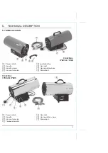
Page 9: ... Power switch Handle Gas control valve Temperature dial Gas inlet Gas regulator hose Mains lead Power switch Handle Handle screws Gas control valve Ignitor button Gas inlet Gas regulator hose Mains lead Stock Nos 17681 17682 Stock Nos 17684 17685 ...

Page 10: ...he Draper Helpline the telephone number appears on the Title page and do not attempt to use the tool The packaging material should be retained at least during the guarantee period in case the machine needs to be returned for repair Warning Some of the packaging materials used may be harmful to children Do not leave any of these materials in the reach of children If any of the packaging is to be th...

Page 11: ...ver check with a flame Propane and butane are heavier than air If there is a leakage it sinks to the lowest possible level collecting there with the surrounding air forming a potentially explosive mixture It is prohibited to use these gas heaters in high rise flats bedrooms bathrooms basements or below ground level 8 2 VENTILATION FIG 2 WARNING Be sure that the heater is only ever used with correc...

Page 12: ...or and gas hose according to the specification on the rating plate Use only BS 3016 approved gas regulator and BS 3212 approved gas hose Gas hose should be in its natural form without excessive bending and not twisted or kinked ensure all connections are gas tight WARNING When connecting to the gas cylinder ensure the area is flame free to prevent risk of explosion Screw fasten the gas hose with r...

Page 13: ...heck valve on the propane tank will stop the gas flow If this happens close the propane supply valve and open again slowly WARNING MAKE SURE THAT THE MOTOR AND FAN ARE RUNNING BEFORE PUSHING IN AUTOMATIC CONTROL VALVE BUTTON FLAMES COULD FLASH OUTSIDE HEATER IF THE MOTOR AND FAN ARE NOT RUNNING 6 Push in and hold the automatic control valve button 7 Push the piezo ignitor button You may need to pu...

Page 14: ... close propane supply valve on propane tank s The heater will burn away gas left In supply hose 2 Allow the heater to cool down for 5 minutes then switch off the heater 3 Unplug the heater TO RESTART THE HEATER 1 Wait five minutes after stopping the heater 2 Repeat steps under To Start The Heater ...

Page 15: ...sity control valve to a low setting 5 Set the fan switch to the ON I position Confirm the fan operates 6 Hold in the gas valve button until the thermocouple is energised and the heater ignites 7 If the heater fails to ignite there may be air in the hose so keep the fuel valve open and wait for about 15 seconds Walt 30 seconds for unburned fuel to exit the heater Repeat the step above 8 When the bu...

Page 16: ...er valve s 2 Let the heater run while any gas left in the supply hoses is burnt off 3 Allow the fan to run for 2 3 minutes with the burner off in order to allow the casing to cool down and the fan to disperse any residual gas 4 Switch off the fan and unplug from the electrical supply 5 Disconnect the gas supply ...

Page 17: ...essary this has to be done by the manufacturer or his agent in order to avoid a safety hazard Remove the plug from the socket before carrying out any adjustment servicing or maintenance Keep the heater clean especially the motor grid and fan blades Store the heater in a dry clean and safe place away from the reach of children The heater should be inspected at least once a year by a qualified perso...

Page 18: ...as not heated enough 2 Safety thermostat activated 3 Restricted air flow 1 Repeat ignition process and keep safety gas valve depressed for a minimum of 5 seconds then release slowly 2 Allow the heater to cool down for at least 10 minutes Check thermostat and then attempt re light sequence correctly 3 Check heater inlet outlet remove any obstructions 1 Replace new gas cylinder 2 Open the valve 3 At...

Page 19: ...repaired ensure that it is disposed of according to national regulations Contact your local authority for details of collection schemes in your area In all circumstances Do not dispose of power tools with domestic waste Do not incinerate Do not abandon in the environment Do not dispose of WEEE as unsorted municipal waste Waste Electrical Electronic Equipment Warning Read instruction manuals before...

Page 20: ... U K Helpline 023 8049 4344 Sales Desk 023 8049 4333 General Enquiries 023 8026 6355 Service Warranty Repair Agent For aftersales servicing or warranty repairs please contact the Draper Tools Helpline for details of an agent in your local area YOUR DRAPER STOCKIST PJMC0616 drapertools com ...

Reviews: