background image

- 6 -

ASSEMBLY

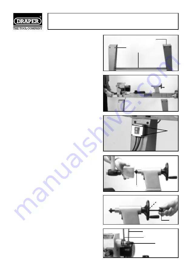
Wood Lathe Stand

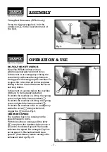
Using the nuts and bolts supplied, fix
together both the top plates 

✪✌

with the four

legs 

✫✌

. Bolt on the shelf (WTL95) or four

supports (WTL90) 

✬✌

and tighten all the

fixings.

Fig.2.

Note: The Wood Lathe stand should always
be fastened down securely to the floor
using four suitable fixings (not supplied).

Mounting the Wood Lathe to the Stand

Lift the lathe onto the stands top plates (seek
assistance as this is very heavy). Align the
holes in the bed with the stand and bolt in
place using the 8 fixings supplied.

Fig.3.

No-Volt On/Off Switch

The no-volt switch is recommended to be
fixed into place on the leg of the stand using
the two bolts 

✭✌

which are longer, coming

through the rear of the switch box.

Fig.4

.

Note: Make sure the cable from the switch
to the motor will allow the rotation of the
headstock. Ensure the lead never passes
between bed and workpiece.

Drive Spur and Live Centre

Locate the drive spur (with prongs) and the
live centre (with bearing) from the
packaging. Insert the live centre 

✮✌

into the

barrel of the tail stock and with a piece of
scrap timber and a hammer, tap the spur in
until secure. Carry out the same procedure
for the drive spur into the headstock spindle.

Fig.5

.

Removal

When the need arises to remove the spurs,
use the ejection pin 

✯✌

to push out the live

centre from the tailstock by inserting it down
the centre of the tailstock handwheel hole

✰✌

.

Fig.6

.

The drive spur is removed using the ejection
pin 

✱✌

and the spindle holding wrench 

✲✌

.

Using the wrench to hold the spindle on the
flats, insert the ejection pin into the hole in
the side of the thread protection cap 

✳✌

.

Undo the cap which will force the spur out of
the spindle.

Fig.7

.

Fig.2.

Fig.3.

Fig.4.

Fig.5.

Fig.6.

Fig.7.

✬✌

✫✌

✭✌

✮✌

✰✌

✯✌

✱✌

✲✌

✳✌

✪✌

Summary of Contents for 39042

Page 1: ...nd safe use We recommend that this manual is read before any operation of the machine before performing any kind of adjustment to the machine and prior to any maintenance tasks By following all the general safety instructions contained in this manual it will ensure both machine and operator safety together with longer life of the tool itself All photographs and drawings in this manual are supplied...

Page 2: ... 16 Optional Accessories 17 Troubleshooting 18 We Draper Tools Ltd Hursley Road Chandler s Ford Eastleigh Hampshire SO53 1YF England Declare under our sole responsibility that the product Stock No 39042 63938 Part No WTL90 WTL95 Description Variable Speed Wood Lathe To which this declaration relates is in conformity with the following directive s 98 37 EEC 89 336 EEC With reference to BS EN 61029 ...

Page 3: ...e of purchase Should the machine develop any fault please return the complete tool to your nearest authorized warranty repair agent or contact Draper Tools Limited Chandler s Ford Eastleigh Hampshire SO53 1YF England Telephone 023 8026 6355 If upon inspection it is found that the fault occurring is due to defective materials or workmanship repairs will be carried out free of charge This guarantee ...

Page 4: ...ug with bare flexible wires exposed is hazardous if engaged in a live power socket outlet WARNING THIS APPLIANCE MUST BE EARTHED Green Yellow Earth Blue Neutral Brown Live As these colours may not correspond with the coloured markings identifying the terminals in your plug proceed as follows The wire which is coloured green yellow must be connected to the terminal in the plug which is marked with ...

Page 5: ... as cutters etc 16 AVOID ACCIDENTAL STARTING Make sure the switch is in the OFF position before plugging the machine into the power supply 17 NEVER LEAVE MACHINE RUNNING UNATTENDED Turn power off Do not leave machine until it comes to a complete stop 18 DO NOT ABUSE THE CORD Never carry the tool by the power cable or pull it from the socket Keep the power cable away from heat oil and sharp edges 1...

Page 6: ... of moving parts 4 Only use Draper approved accessories and spares 5 Keep turning chisels sharp 6 Keep pulley cover guards in place when working 7 Never reach behind or beneath the workpiece 8 Unplug from power supply before adjusting or servicing 9 To avoid electric shock do not use in damp conditions or expose to rain 1 Motor 2 Head Stock 3 Tail Stock 4 Stand 5 Tool Rest 6 Bed 7 Bed extension WT...

Page 7: ...om the switch to the motor will allow the rotation of the headstock Ensure the lead never passes between bed and workpiece Drive Spur and Live Centre Locate the drive spur with prongs and the live centre with bearing from the packaging Insert the live centre into the barrel of the tail stock and with a piece of scrap timber and a hammer tap the spur in until secure Carry out the same procedure for...

Page 8: ...power failure the machine will have to be manually restarted To switch the machine on lift up the sprung cover and push the button marked To switch the machine off lift up the sprung cover and push the button marked To switch the machine off in an emergency strike the cover firmly which will trigger the button Fig 9 CHANGING SPEED The machine has to be running for the speed change to move With the...

Page 9: ...t of the tool rest loosen handle This set up with the tool rest will provide for most of your needs However should it be required for bowl turning etc there is an extension provided This fits by loosening handle Remove the tool rest and replace with the extension Loosen handle on the extension and slide in tool rest When fully adjusted make sure all of the locking handles are secured Fig 14 CHANGI...

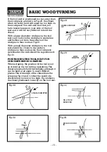
Page 10: ... workpiece in a soft jaw vice Put the point of the drive spur into the drilled hole and tap the spur in securely Fig 17 Now remove the spur and check the prongs have left an imprint Ensure that both the drive spur and live centre are clean and insert them into the lathe see Page 6 Place the workpiece between the centres and close up the tailstock Fig 18 making sure the marked end goes the headstoc...

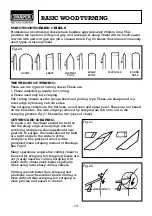
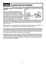
Page 11: ...ire edges produced by scraping are left on to aid in the scraping process Fig 21 Shows the two types of chisel CUTTING AND SCRAPING To make a cut the chisel should be held so that the sharp edge actually digs into the revolving workpiece shavings should now peel off To scrape the chisel should be held at a right angle to the surface of the workpiece fine pieces of wood will be produced when scrapi...

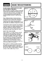
Page 12: ...hen the method used is towards the circumference the shaving will come off like the peel from a potato Only scraping can be used when the method used is towards the diameter The reason for this is obvious when you consider that faceplate turning nearly always requires the removal of wood across the grain Wood does not peel easily when turning across the grain and any attempt made to use cutting me...

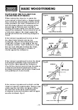
Page 13: ...e Fig 25 the cutting edge of the chisel will continue to dig deeper into the workpiece until the bite becomes so deep that you have difficulty holding the chisel then the chisel will begin to bounce or chatter against the workpiece If the tool rest is positioned too low the chisel will be held extremely high to position the bevel of the chisel against the workpiece Fig 26 then the tool rest will l...

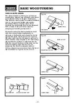
Page 14: ...rkpiece the tool rest should be closer to the surface workpiece than normal As the workpiece gets smaller the rest should be repositioned Fig 30 POSITIONING THE TOOL REST FOR CIRCUMFERENCE SCRAPING When scraping the position of the tool is not as critical as it is for cutting operations The chisel is normally held horizontally although it can be held at an angle to reach difficult places The wire ...

Page 15: ...he position in which it is easiest to hold the chisel steady To obtain the position place the rest approximately 3mm below the centre USING THE GOUGE CHISEL Three gouges 6 12 18mm sizes are usually sufficient for home workshop turning but other sizes are available refer to Draper Catalogue A gouge chisel is normally used for rough circumference turning or turning raw stock down to a cylinder of wo...

Page 16: ...ting the skew should be held with the cutting edge considerably in advance of the handle and should be bevel against the work Good practice is to place the skew well over the workpiece and pull it back until the edge begins to cut then swing the handle into position to advance the cut Both the toe and the heel of the skew can be used for making light cuts but do not penetrate the wood too deeply w...

Page 17: ... chisel should complete the list of chisels for the average craftsman these are 12mm spear point 12mm round nose and 26mm flat nose Each of these chisels may be purchased in various sizes refer to the Draper Catalogue for special jobs All of these are very useful for diameter scraping see Figs 45 46 47 operations and for circumference scraping when cutting methods cannot be employed The spear poin...

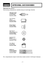
Page 18: ...o 29422 Cup Turning Chuck Part No AWL2 Stock No 29423 Screw Chuck Part No AWL3 Stock No 29424 Right Hand Thread Face Plate Part No AWL8 Stock No 29429 Combination Chuck Part No AWL40 Stock No 37168 Face Shield Part No FS8 Stock No 33831 HSS Wood Turning Chisels Part No AWL44 Stock No 58697 For a comprehensive range of wood lathe accessories refer to the Draper Catalogue ...

Page 19: ...fore using lathe again Defective switch cord 3 Burned out motor 3 Any attempt to repair this motor may cause a Hazard unless the repair is done by a qualified service technician Headstock loose on 1 Locking handle not 1 Tighten locking handle bed tight Wood burns at tailstock 1 Live centre too tight or 1 Back of tailstock barrel and lubricate live centre end not lubricated See Basic Lathe Operatio...

Page 20: ...6355 Fax 023 8026 0784 http www draper co uk e mail sales draper co uk Published by Draper Tools Ltd No part of this publication may be reproduced stored in a retrieval system or transmitted in any form or by any means electronic mechanical photocopying recording or otherwise without prior permission in writing from Draper Tools Ltd YOUR DRAPER STOCKIST ...

Reviews: