INSTRUCTIONS FOR
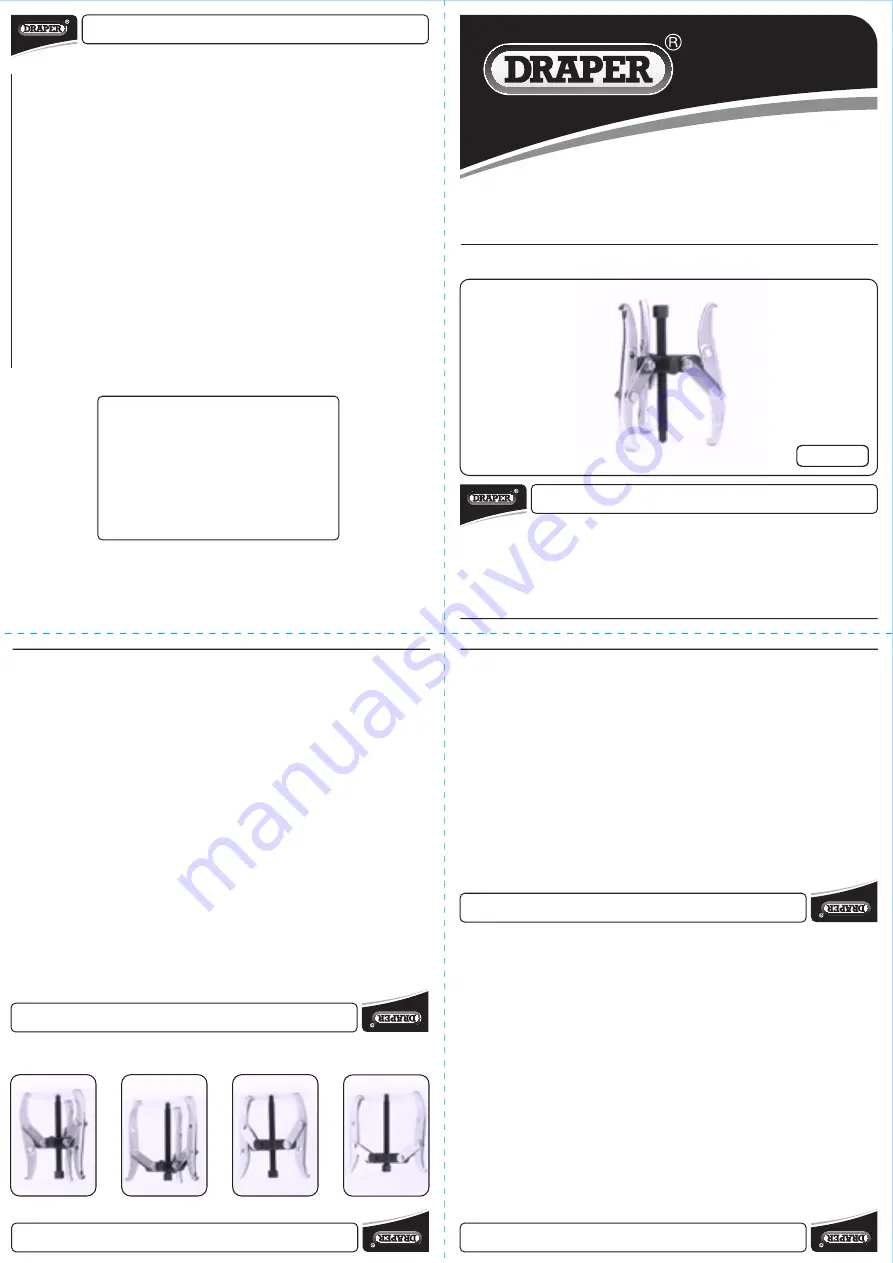
Twin/Triple
Reversible Puller
Stock No.56177 Part No.N136
This manual has been compiled by Draper Tools and is an integrated part of the product with which it is enclosed and
should be kept with it for future references.
This manual describes the purpose for which the product has been designed and contains all the necessary information
to ensure its correct and safe use. We recommend that this manual is read before any operation or, before performing
any kind of adjustment to the product and prior to any maintenance tasks. By following all the general safety instructions
contained in this manual, it will ensure both product and operator safety, together with longer life of the product itself.
All photographs and drawings in this manual are supplied by Draper Tools to help illustrate the operation of the product.
Whilst every effort has been made to ensure accuracy of information contained in this manual, the Draper Tools policy of
continuous improvement determines the right to make modifications without prior warning.
IMPORTANT:
PLEASE READ THESE INSTRUCTIONS CAREFULLY TO ENSURE THE SAFE AND
EFFECTIVE USE OF THIS PRODUCT.
CONTACTS
GENERAL INFORMATION
11/2004
-
DRAPER TOOLS LIMITED,
Hursley Road,
Chandler's Ford,
Eastleigh,
Hampshire.
SO53 1YF. U.K.
-
Helpline:
(023) 8049 4344.
-
Sales Desk:
(023) 8049 4333.
-
General Enquiries:
(023) 8026 6355.
-
Fax:
(023) 8026 0784
-
Internet:
www.draper.co.uk
-
E-mail:
sales@drapertools.com
YOUR DRAPER STOCKIST
©Published by Draper Tools Limited.
No part of this publication may be reproduced, stored in a retrieval system or
transmitted in any form or by any means, electronic, mechanical photocopying,
recording or otherwise without prior permission in writing from Draper Tools Ltd.
- 2 -
VERSATILITY
SAFETY
-
INFORMATION:
1.
Application of pressur
e on the forcing
screw incr
eases the grip of the
self-locking legs.
2.
By reversing the legs the amount of r
each
and spread can be varied to suit the job.
3.
The link nuts of this puller must not be
locked tight, as this will prevent the self-
locking action.
4.
Always clean and lubricate the forcing
screw befor
e and after use.
-
INSTRUCTIONS:
1.
Withdraw the forcing scr
ew to provide
sufficient reach.
2.
Ensure the puller is located at the centr
e
of the workpiece before applying any
pressur
e on the forcing scr
ew.
3.
Locate the reversible legs ar
ound the
workpiece. Hand tighten the
forcing scr
ew.
4.
Check that the puller is centrally located
and that the forcing scr
ew is lined up
with the axis of the shaft.
5.
Continue to apply pressur
e using the
correct size of spanner or socket on the
hexagon head of the forcing scr
ew.
6.
Hit the striking head of the forcing scr
ew
with a soft faced hammer and then re-
tighten with a spanner or socket.
7.
Continue this operation until the
workpiece is removed.
-
IMPORTANT
:
Trying to r
emove items by using the forcing
screw alone will str
ess the triple head and
screw thr
ead causing damage. For detailed
and concise instructions on the correct use
of this tool, refer to the vehicle
manufacturer’
s handbook.
-
SAFETY FIRST:
A. Ensur
e the tool is fitted squarely to
workpiece.
B.
Do not use excessive pressur
e.
C.
Avoid injur
y or damage due to sudden
release of pr
essure or r
esistance.
D.
Attempt to cover the puller and item
being pulled as a precaution against
flying debris.
E.
Take pr
ecautions against any sudden loss
of balance caused by the release of
pressur
e.
- 1 -
SPECIFICATION
The Draper Tools policy of continuous impr
ovement determines the right to change specification
without notice.
Stock No. ......................................................................................................................... 56177
Part No........................................................................................................................
...... N136
Maximum Reach............................................................................................................. 150m
m
Maximum Spread
............................................................................................................ 100mm
Two Leg
Short Leg
Reach............................................................................................................ 75mm
Spread
.......................................................................................................... 150mm
Long Leg
Reach.......................................................................................................... 120mm
Spread
.......................................................................................................... 150mm
Three Leg
Short Leg
Reach............................................................................................................ 75mm
Spread
.......................................................................................................... 150mm
Long Leg
Reach.......................................................................................................... 120mm
Spread
.......................................................................................................... 150mm
GUARANTEE
Draper tools have been carefully tested and inspected befor
e shipment and are guaranteed to be
free fr
om defective materials and workmanship.
Should the tool develop a fault, please return the complete tool to your near
est distributor or
contact Draper Tools Limited, Chandler's For
d, Eastleigh, Hampshire, SO53 1YF
. England.
Telephone: (023) 8026 6355.
If upon inspection it is found that the fault occurring is due to defective materials or
workmanship, repairs will be carried out fr
ee of charge. This guarantee period covering
parts/labour is 12 months from the date of pur
chase. The guarantee is extended to 24 months
for parts only. This guarantee does not apply to normal wear and tear , nor does it cover any
damage caused by misuse, careless or unsafe handling, alterations, accidents, or r
epairs
attempted or made by any personnel other than the authorised Draper warranty repair agent.
This guarantee applies in lieu of any other guarantee expressed or implied and variations of its
terms are not authorised.
Your Draper guarantee is not effective unless you can pr
oduce upon request a dated r
eceipt or
invoice to verify your proof of pur
chase within the guarantee period.
Please note that this guarantee is an additional benefit and does not affect your statutory rights.
Twin long leg.
Twin short leg.
Triple long leg.
Triple short leg.


