background image

14

9.1 PRELIMINARY OPERATIONS

–   Completely deflate the tyre. 
 

WARNING: If tyre pressure monitoring sensors (TPMS) are fitted to the tyre, the pressure 
must be released slowly. Sudden loss of pressure may damage the sensors. Always check 
with the vehicle manufacturer before deflating tyre.

–   Remove wheel balancing weights to avoid any interference with the clamping 

mechanism.

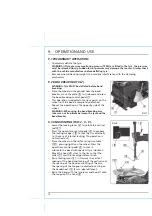
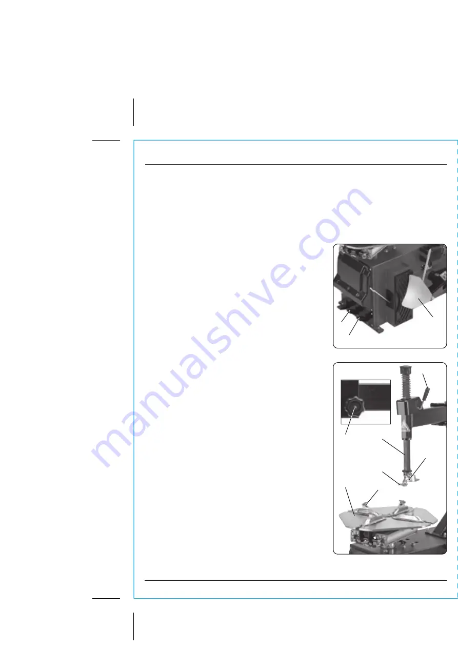
9.2 BEAD BREAKING (FIG.7).


WARNING: Tyre MUST be deflated before bead 
breaking.

–   Place the wheel on the ground near the bead 

breaker, move the plate 

 to the bead and press 

the bead breaking control pedal 

.

–   This operation is repeated at various points on the 

wheel until the bead is completely detached.

–   Repeat the operation on the opposite side of the 

wheel.


WARNING:


When using the bead breaking arm, 

take care not trap limbs between the tyre and the 
bead breaker.

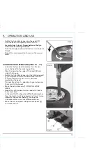
9.3 UNMOUNTING (FIGS.7, 8 – 9).

–   Lower the locking lever 

 to unlock the vertical 

rod 

.

–   Press the open/close control pedal 

 to prepare 

the locking wedges 

 to lock the rim externally 

(in the case of internal locking, this operation is 
not carried out).

–   Place the wheel on the self-centring turntable 

, pressing lightly on the wheel. Press the 

open/close control pedal 

 to lock it.

–   Lubricate the bead with specialist tyre lubricant.
–   Move the head 

 close to the rim so that the 

roller 

 and the rim edge surface touch.

–   Raise locking lever 

: in this way the vertical 

spacing of the head and locking of the vertical rod; 
the spacing of the head and locking of the arm; 
the spacing of the tongue is adjusted by acting on 
the handwheel 

 (3 mm ideal distance:).

–   Raise the bead with the tyre lever and hook it onto 

the tongue of the head 

.

9.   OPERATION AND USE

FIG.7

FIG.8

Summary of Contents for 81645

Page 1: ...is manual has been compiled by Draper Tools describing the purpose for which the product has been designed and contains all the necessary information to ensure its correct and safe use By following all the general safety instructions contained in this manual it will ensure both product and operator safety together with longer life of the product itself AlI photographs and drawings in this manual a...

Page 2: ...RSTANDING THIS MANUALS SAFETY CONTENT WARNING Information that draws attention to the risk of injury or death CAUTION Information that draws attention to the risk of damage to the product or surroundings NOTE Important information 1 4 COPYRIGHT NOTICE Copyright Draper Tools Limited Permission is granted to reproduce this publication for personal educational use only Commercial copying redistributi...

Page 3: ...ER 6 1 IDENTIFICATION 9 7 UNPACKING CHECKING 7 1 PACKAGING 10 8 INSTALLATION AND ASSEMBLY 8 1 DETERMINE THE PROPER LOCATION FOR THE TYRE CHANGER 11 8 2 MOUNT THE TYRE CHANGER ON A FLOOR SURFACE 11 8 3 ATTACHING THE COLUMN 12 8 4 SETTING THE SPRING ON THE VERTICAL ROD 12 8 5 PNEUMATIC CONNECTION 13 8 6 ELECTRICAL CONNECTION 13 9 OPERATION AND USE 9 1 PRELIMINARY OPERATIONS 14 9 2 BEAD BREAKING 14 9...

Page 4: ...hase except where tools are hired out when the guarantee period is ninety days from the date of purchase This guarantee does not apply to normal wear and tear nor does it cover any damage caused by misuse careless or unsafe handling alterations accidents or repairs attempted or made by any personnel other than the authorised Draper warranty repair agent Note If the tool is found not to be within t...

Page 5: ...TORAGE To maintain machine and user safety the responsibility of the owner is to read and follow these instructions Follow all installation instructions Make sure installation conforms to all applicable local environmental health and safety rules and regulations Carefully check the unit for correct initial function Read and follow the safety instructions Keep them readily available for machine ope...

Page 6: ... all cases do not operate power tools near any flammable materials Beware of electric shock Avoid contact with earthed surfaces because they can conduct electricity if there is an electrical fault with the power tool Always protect the power cable and route it away from danger Keep bystanders away Children onlookers and passers by must be restricted from entering the work area for their own protec...

Page 7: ...d will result in injury Maintain your tools correctly A well maintained tool will do the job safely Replace any damaged or missing parts immediately with original parts from the manufacturer As applicable keep blades sharp moving parts clean oiled or greased handles clean and emergency devices working Wait for the machine to stop Unless the machine is fitted with a safety brake some parts may cont...

Page 8: ...il and other debris Do not use the tyre changer in a damp or wet location Do not use the tyre changer in areas near flammable chemicals dusts and vapours This tyre changer is designed for use with most passenger car and light commercial vehicle wheels Do not attempt to exceed this machine s maximum wheel diameter capacity Always keep hands fingers and feet away from the moving parts of the tyre ch...

Page 9: ...ead breaking plate Bead braking arm Anti abrasion supp Swinging arm Head Locking lever Handwheel Sliding roller Locking wedges Slide tracks Air inflation gun Air moisture filter Oil lubrication level reservoir Air pressure regulator Air pressure gauge Tyre lever Turntable 6 1 IDENTIFICATION ...

Page 10: ...uld be retained at least during the guarantee period in case the machine needs to be returned for repair Warning Some of the packaging materials used may be harmful to children Do not leave any of these materials in the reach of children If any of the packaging is to be thrown away make sure they are disposed of correctly according to local regulations 7 UNPACKING CHECKING ...

Page 11: ...d for indoors use only Do not install or use outdoors or in damp or wet locations Make sure to check the desired location for possible obstructions such as a low ceiling overhead lines adequate working area access ways exits etc The tyre changer MUST be located in an area free of flammable materials and liquids 8 2 MOUNT THE TYRE CHANGER ON A FLOOR SURFACE FIG 2 The machine is fitted with special ...

Page 12: ...mm hex key Warning when unscrewing the rod take the precaution of keeping one hand underneath it Remove the rod Slide the spring off and re insert the rod in its original seating locking it at the end of its travel Insert the spring on the top of the rod and refit the cap FIG 3 8 3 ATTACHING THE COLUMN FIG 3 Fix the column to the machine body using the bolts in the machine CAUTION The column is ve...

Page 13: ...air supply to the coupling located between the lubricator and the air filter FIG 5 FIG 6 8 6 ELECTRICAL CONNECTION FIG 6 WARNING All work on the electrical system including minor operations must be carried out by professionally qualified personnel Check that the electrical supply voltage is the same as that indicated on the rating label situated at the back of the machine ...

Page 14: ...When using the bead breaking arm take care not trap limbs between the tyre and the bead breaker 9 3 UNMOUNTING FIGS 7 8 9 Lower the locking lever to unlock the vertical rod Press the open close control pedal to prepare the locking wedges to lock the rim externally in the case of internal locking this operation is not carried out Place the wheel on the self centring turntable pressing lightly on th...

Page 15: ...d on the edge of the head and under the tongue Rotate the turntable by pressing the rotation pedal taking care to make the bead move into the central groove of the rim so as to eliminate weakening the bead To help this action it is advisable to press down on the tyre with the hands Move the adjustable arm TO FREE THE WORK AREA Repeat the initial operation see above to locate the second bead In the...

Page 16: ...9 5 INFLATING OPERATIONS FIG 12 WARNING THE INFLATION PROCESSES IS POTENTIALLY DANGEROUS THE OPERATOR MUST ADOPT ALL THE MEASURES NECESSARY IN ORDER TO GUARANTEE SAFE CONDITIONS 9 OPERATION AND USE FIG 12 ...

Page 17: ...rect connection in the plug 3 Electrical supply not suitable 1 Supply voltage wrong 2 Slack drive belt 1 The pneumatic supply is not connected to the machine 2 Insufficient pressure in the pneumatic system 3 Pressure regulator is closed or badly adjusted 1 The pneumatic supply is not connected to the machine 2 Insufficient pressure in the pneumatic system 3 Pressure regulator is closed or badly ad...

Page 18: ...operation remove the plug from the electrical socket Mechanical parts Keep the moving parts clean and lubricating them with oil or grease In particular Lubricator Check and maintain the level of oil in the lubricator The level must not go outside the min max indicated If necessary add air tool oil Air filter Periodically remove the water condensation that forms in the air filter Roller Check that ...

Page 19: ...electrical supply If it is decided that this machine is no longer to be used it is advisable to make it inoperative by removing the electrical cable after having disconnected the plug from the supply At the end of the machine s working life or when it can no longer be repaired ensure that it is disposed of according to national regulations Contact your local authority for details of collection sch...

Page 20: ... Desk 023 8049 4333 Website www drapertools com E mail sales drapertools com Sales Fax 023 8049 4209 General Enquiries 023 8026 6355 Service Warranty Repair Agent For aftersales servicing or warranty repairs please contact the Draper Tools Helpline for details of an agent in your local area YOUR DRAPER STOCKIST DBCH0715 ...

Reviews: