– 14 –
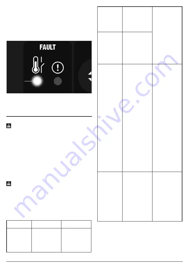
8.7 THERMAL CUT-OUT – FIG.13
If welding for extended periods, the thermal cut-out will
activate and the LED indicator
(M)
will illuminate,
prohibiting use of the machine until sufficiently cool.
Caution! After completion of any welding task, leave the
unit connected to the power supply for a sufficient period
to allow the cooling fan to continue working.
13
FIG.
9. MAINTENANCE AND
TROUBLESHOOTING
9.1 MAINTENANCE
Warning!
If the welding machine has just been turned off, you
must not conduct any internal checks or
maintenance for at least 5 minutes after the power
distribution box switch or power switch is
disconnected so that the capacitor inside the
welding machine is completely discharged.
− It is crucial to carry out regular checks on this product
to ensure optimum performance and safe operation.
− The inspection table below offers guidance for the
checking of components for general wear and tear or
damage. Wherever necessary, clean or replace such
items.
Warning! Any live electrical parts touched may
cause fatal electric shock or serious burns.
For your own safety, turn the switch off and remove the
plug from the power supply socket when carrying out
any form of maintenance or cleaning. If in doubt, consult
Draper Tools, or an authorised service agent.
Welding power supply:
Component
Check points
Advisories
Front panel
− Check if any
components
are
damaged or
loose.
Tighten or
replace where
necessary
Front panel
− Check if the
lower quick
socket is
loose.
The lower quick
socket is a
regular item. If a
defect occurs, it
will be
necessary to
check the
inside, re-fasten
or replace
components
where
necessary.
Rear panel
− Check if the
air intake of
the cooling
fan has
foreign
objects
sticking to it.
Routine
− Power on,
and then
check if the
appearance
has fading or
too hot
traces.
− Check if the
cooling fan
has stable
operation
sound.
− Check if the
cooling fan
takes in air
from the air
intake, if
odour,
abnormal
vibration or
noise
(especially
during
welding)
occurs.
In-case of
defects, it is
necessary to
check the inside
of the device.
Top plate,
bottom
plate and
side panel
− When the
machine
cover is
installed
onto the
housing,
check if it is
loose.
− Check if
bolts are
loose.
In case of
defects, it is
necessary to
replace or
fasten
components,
etc., as
required.
(M)
Summary of Contents for Expert 70052
Page 18: ......


