EZ-Fold Basketball Backstops by Draper—Wall-Mounted
Page 5 of 18
www.draperinc.com
(765) 987-7999
T
w
ist lock receptacle (3 prong)
4" s
qu
are
b
ox, and co
v
er plate
(all
b
y others)
10"
3½"
8
¼"
110-120
v
AC radio controlled
recei
v
er (1 pro
v
ided for
each
w
inch re
qu
ired)
Backstop or gym
di
v
ider selector s
w
itch
“Up-Do
w
n”
bu
ttons
Receptacle (4-prong) to
accept po
w
er/control ca
b
le
from 1 H.P. electric
w
inch
-Pl
u
g pro
v
ided
b
y man
u
fact
u
rer
66" long cord 14A
W
G3/CSJ
Hand held porta
b
le transmitter:
503020 – Operates
u
p to 9
w
inches
503021 – Operates
u
p to 27
w
inches
W
eight 7 oz.
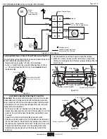
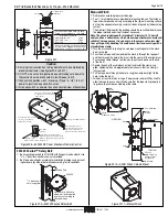
Figure W-7
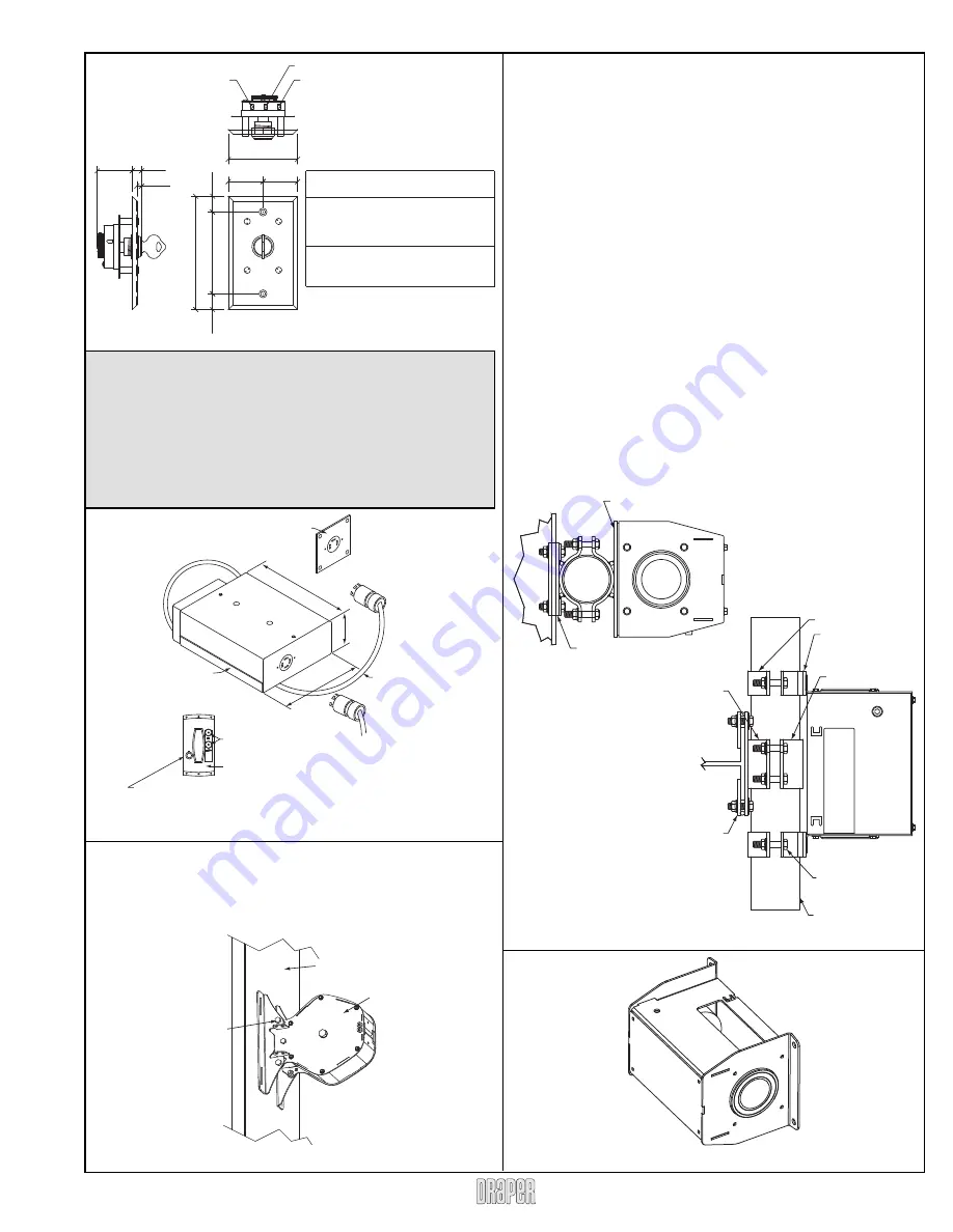
Figure W-8—503023 EZ Power Electronic Remote Control
Caution
➀
All wiring from junction box to Key Switch must be completed by
electrical contractor (see fi gures W-3 and W-7).
➁
DO NOT wire winch into junction box until making sure power to
the
junc
tion box is disconnected (circuit breaker is off).
➂
If key switch operates winch in reverse (“Down” is “Up”), turn off
power to junction box and switch wires.
➃
Install key switch so operator has unobstructed view of backstops.
Circ
u
it
b
reaker rated amp. 20 amp.
F
u
sed circ
u
it rated amp. 20 amp.
Minim
u
m
W
ire Size
90
'
maxim
u
m r
u
n. . . . . . . . . 12 ga.
90
'
to 140
'
r
u
n. . . . . . . . . . . .10 ga.
O
v
er 140
'
. . . . . . . . . . . . . . . .
8
ga.
Sizes of
w
all masonry
b
oxes re
qu
ired
for single and ganged key s
w
itches--
All
b
oxes 2" (
w
) x 3¾" (h) x 2½" (d).
1
3
/
8
"
3
/
8
"
3
/
16
"
1
3
/
8
"
1
3
/
8
"
4
1
/
2
"
3
1
/
4
"
5
/
8
"
5
/
8
"
2
3
/
4
"
12 (Do
w
n)
11 (Black/Hot)
1
8
(Up)
Manual Winch
➀
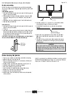
Find location according to project drawings.
➁
Four
9
/
16
" diameter holes are provided for mounting the unit. The fastener
type and size required will vary according to the type of mounting surface
but must be adequate to safely sustain all loads imposed by the backstop
system.
The Architect/ Engineer for the building should be consulted to determine
the proper method and size of fastener necessary.
Note: The winch is designed for standard ¼" diameter 7 x 19 aircraft
cable and has a hollow drum, which makes rope attachment simple and
reliable. The rope passes through a hole in the drum and is prevented
from pulling out by doubling the end back on itself and securing with a
standard rope clamp.
➂
Turn the winch handle to bring the wire rope mounting hole in the winch
drum to the top.
➃
Pass the wire rope end from outside the winch in through the rope port
and then through the hole in the drum, into the center of the hollow drum.
Pass enough cable through to allow you to pull the free end out the end
of the drum.
➄
Double the end of the cable back on itself and install the clamp sup-
plied, tightening the nuts progressively to make sure that the clamp is
fully
secured.
➅
Pull the rope back through the hole to snug the clamp back tight to the
hole, inside the drum.
➆
Wind on at least two turns of rope. (The pressure roller will lift by itself to
allow the rope to pass under.) Make sure that the rope starts properly in
its groove, to ensure even winding of the cable.
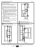
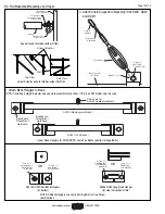
Figure W-10—A0481 Winch Column Mount
503029 Posilok™ Safety Belt:
➀
Bolt mounting brackets to POSILOK with fl anges turned outward. Use
3
/
8
" x 1" bolts, lock washers and nuts provided.
➁
Bolt to wood wall pads according to installation drawings using mount-
ing hardware (by others) determined according to site conditions.
Figure W-9—503029 Posilok Safety Belt
Figure W-11—Manual Winch
W
ood Pad
503029
Hard
w
are to attach to
w
ood
w
all pad s
u
pplied
b
y others according to
site conditions
3
/
8
"
b
olts and
n
u
ts (s
u
pplied)
4" x 2" Half Clamp
A0481
Bracket
4" x 4" Half Clamp
A0340
Spacer
Flat
1/2"-13 x 2"
Grade 5 Cap Screw
& Flange Lock Nit
Typ. (8) places
TOP VIEW
4" O.D. Tubing
A0481
Bracket
A0340
Clamped to column
SIDE VIEW

