Section 1 -
Mounting Shade
Caution:
Before mounting shades, verify measurements on label provided with shade,
and ensure unit is installed at correct width.
Please Note:
•
Installer is responsible for selecting mounting hardware appropriate for site conditions.
• Ensure that shade is kept clean.
• Ensure that shade is installed level
(using a carpenter’s level)
.
• Operating switch
(es)
are packed separately in shade carton. Do not discard with
packing material.
• Shade operates on 110-120V, 60 Hz. current.
• Shade has been thoroughly inspected and tested at factory and found to be operating
properly prior to shipment.
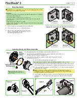
1.
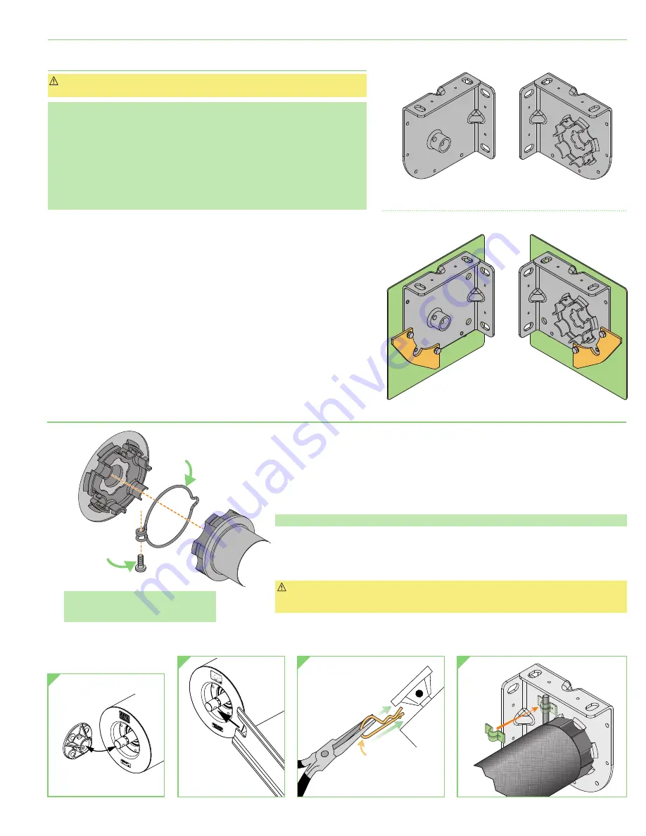
Mark wall, jamb, or ceiling for placement of mounting brackets.
2.
Drill small starter hole
(if necessary)
in mounting surface.
3.
Mount brackets using appropriate fasteners for surface.
Centers of mounting holes are approximately
13/16
"
(21 mm)
from outer edge of endcap/bracket.
1.
Ensure Motor Retainer Ring is expanded around the motor end bracket
(Fig. 2)
.
2.
Place motor/roller assembly in the idler end. Push spring-loaded idler into idler mount
(Fig. 3)
,
then move motor end into motor mounting bracket.
3.
Ensure that Motor Retainer Ring is properly installed around the grooves in the motor
and motor end bracket
(Fig. 2)
.
Section 2 -
Installing Shade and Motor Assembly
4.
Install the Retaining Spring Screw and tighten
(Fig. 2)
.
Please note:
Maximum torque for tightening Retaining Spring Screw is 5 lb-in
(22.24 Nm)
.
5.
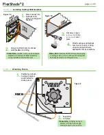
Use the provided spanner wrench to rotate the idler until the holes in the idler match up with the
vertical holes in the idler mounting bracket as seen when looking straight up into the case
(Fig. 4)
.
6.
Using a pair of needle-nosed pliers install the cotter pin
(Fig. 5)
. The pin has a built-in ball detent
to prevent pin from falling out.
Caution:
Cotter pin must be correctly installed to insure safe operation of the shade. If
misalignment of the holes in the idler shaft and bracket prevent the cotter pin from being
installed, remove and re-install roller assembly.
7.
Use the Motor Cable Guide with self-adhesive attachment pads to secure the motor cable to
the endcap
(Fig. 6)
. This will prevent possible damage to the cable by the roller during shade
operation.
MOUNTING BRACKETS
ENDCAPS FOR HEADBOX OR FASCIA
Idler End
(Left Standard)
Motor End
(Right Standard)
Idler End
(Left Standard)
Motor End
(Right Standard)
Figure 1-A
Figure 1-B
Motor
Cable
Guide
Retaining
Spring Screw and
Retaining Spring
Motor
Retainer
Ring
Cotter
Pin
Figure 3
Figure 4
Figure 5
Figure 6
Please note:
Maximum torque for
tightening Retaining Spring Screw is 5
lb-in
(22.24 Nm)
.
Figure 2
page 3 of 8
FlexShade
®
2


