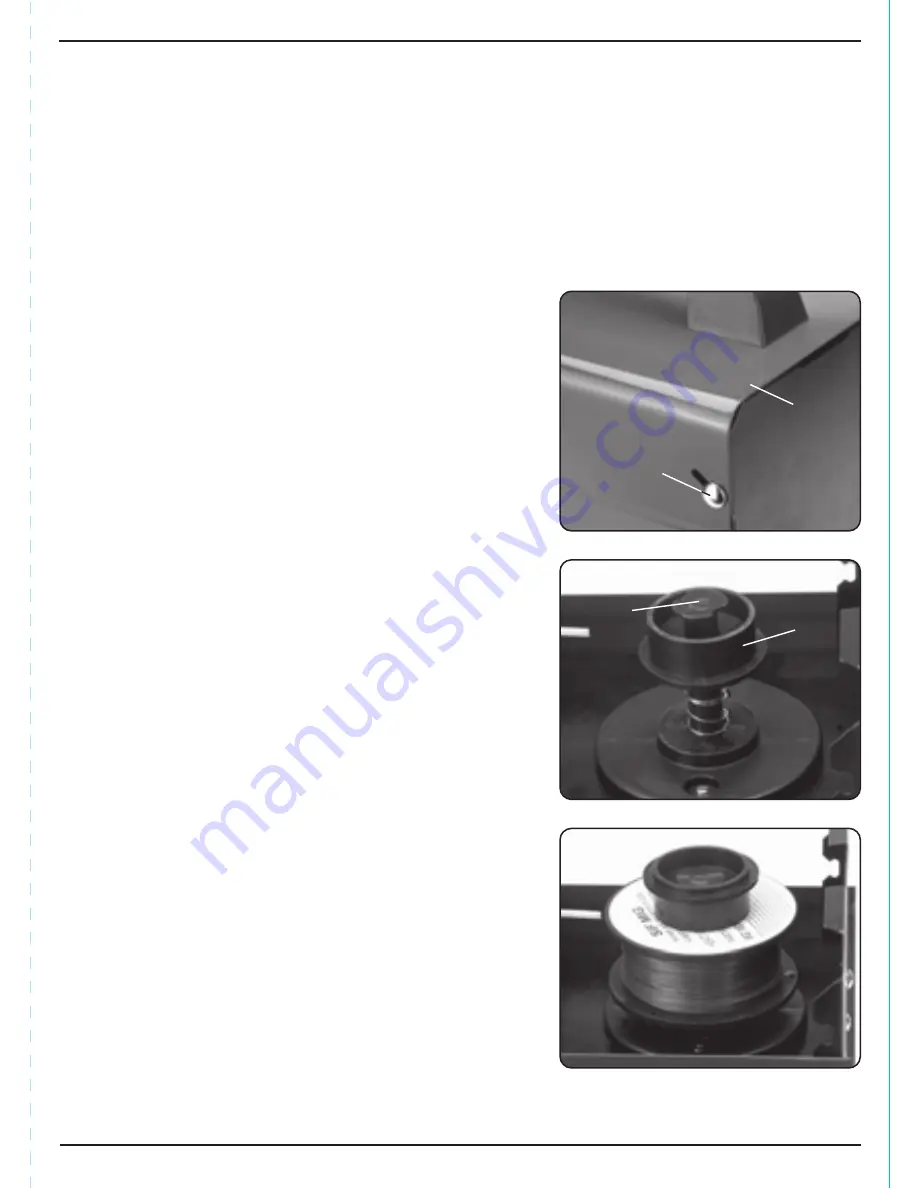
FIG.1
FIG.3
13
8. PREPARING THE WELDER
Warning!
Do not make any adjustments, maintenance or servicing with the machine
connected to the power supply.
8.1 LOCATION
Locate the machine in close proximity to the correct power supply and allow 500mm air gap
around to ensure sufficient ventilation. There is one cooling fan located in the rear of the
machine housing which must be kept clear. Equally, ensure no debris can be drawn into the
machine.
Make certain the location does not pose any hazards as detailed in the safety instructions,
before attempting to start the machine.
8.2 INSTALLING THE FILLER WIRE
– FIGS. 1 – 3
The welding machines are designed to accept the
standard size drums of wire up to 500g.
Do not let the filler wire become uncoiled or tangled
as this will lead to problems with delivery to the
welding torch.
Select the filler wire suitable for the parent metal and
with a gauge to match the welder specification.
Note:
If the welding machine is not regularly used,
remove the wire which is prone to rusting and will
cause feed problems next time.
i. Lift the latch
to release the top cover
.
ii. Remove the large plastic ring
(turning it
clockwise). Sit the reel on to the hub
and
make sure the peg locates in the back of the
reel. Refit the large plastic ring
.
iii. Fit the wire spool so that it feeds off the roll
towards the wire drive unit.
FIG.2
Summary of Contents for MIG100GG
Page 22: ...22 NOTES ...
Page 23: ...23 NOTES ...


